P13 Plateforme expérimentation IOT : Différence entre versions
(→Tâches 6 : Choix des capteurs) |
|||
| (527 révisions intermédiaires par 2 utilisateurs non affichées) | |||
| Ligne 1 : | Ligne 1 : | ||
| + | <include nopre noesc src="/home/pedago/pimasc/include/video-InternetDesObjets-iframe.html" /> | ||
| + | __TOC__ | ||
| + | <br style="clear: both;"/> | ||
==Présentation du projet== | ==Présentation du projet== | ||
| + | ===Contexte=== | ||
| + | Dans un monde qui va devenir connectée, il a été décidé de réaliser un projet sur ces nouvelles technologies. La plateforme pourra être implantée dans la nouvelle bibliothèque universitaire du campus de Lille.<br> Les utilisateurs pourront bénéficier d’informations disponibles tel que les places disponibles, la température, la luminosité … | ||
| + | Ces informations dépendront des capteurs mis sur le nœud.<br><br> | ||
| + | Le deuxième intérêt que l’internet des objets nous procure, c’est l’historique et la prévision. En effet on aura une possibilité de stocker les informations.<br> <br> | ||
| + | Exemple :<br><br> | ||
| + | • Commander le chauffage en fonction des températures extérieures ou d’estimer la consommation par rapport aux années précédentes. <br> | ||
| + | • Effectuer un suivi de la fréquentation de la bibliothèque. Cette fréquentation pourra être analysée afin de mettre plus de personnel lors des périodes de forte affluence comme des jobs étudiant.<br> <br> | ||
| + | Le but de ce projet est de développer une plateforme d’expérimentation. <br> | ||
| − | |||
[[File:pfe_p13_Lilliad.png|500px|thumb|center]] | [[File:pfe_p13_Lilliad.png|500px|thumb|center]] | ||
| − | + | ===Cahier des charges=== | |
| + | Objectif :<br> | ||
| + | -Réaliser un noeud de capteur<br><br> | ||
| − | + | Il a été défini lors des réunions les points suivants :<br><br> | |
| + | -Structure d'un nœud de capteur <br> | ||
| + | Un nœud de capteur sera composé d'une carte mère, de 8 cartes filles . Sur chacune des filles il y aura deux capteurs implantés dessus.<br> | ||
| + | Ci-dessous un nœud de capteur : <br> | ||
| + | [[File:Pfe_p13_noeud_capteur.JPG|300px|thumb|center]]<br><br> | ||
| − | + | -Communication interne du nœud<br> | |
| + | Le noeud sera capable de se recongifurer tout seul via la raspberry.<br> | ||
| + | Par soucis de sécurité on pourra remonter les données issues des capteurs soit par la liaison série ou par liaison usb.Il faut noter | ||
| + | que la liaison USB sera utilisé en fonctionnement normal<br> | ||
| + | Chaque capteur communique en liaisons radios entre eux.<br><br> | ||
| + | |||
| + | -Communication externe du noeud <br> | ||
| + | Le noeud communiquera vers d'autre noeud ou vers un puit grâce à une liaison radio située sur les cartes des petites filles soit via | ||
| + | le cable éthernet placé sur la carte mére.<br><br> | ||
| + | |||
| + | -Information que l'on souhaite avoir <br> | ||
| + | Afin de réaliser un noeud il a été choisi de faire remonter les informations suivantes :<br> | ||
| + | [[File:Pfe_p13_donnees.JPG|300px|thumb|center]]<br><br> | ||
| + | Ces informations correspondent à des données utilisables en bibliothèque pour les étudiants que pour le personnel. Ces données pourront être stockées en vue d'analyse. Ces dernières seront traitées dans le projet P10.<br><br> | ||
| + | |||
| + | ==A la découverte de la programmation PDI== | ||
| + | ===Présentation du PDI=== | ||
| + | Le Programme et Débogue l'Interface (PDI) est une interface propriétaire Atmel pour | ||
| + | la programmation externe et son débogage.Il est constitué de deux éléments: <br> | ||
| + | -Clock<br> | ||
| + | -Data<br><br> | ||
| + | Schéma du connecteur pour la programmation en pdi<br> | ||
| + | <center>[[Fichier: PFE_p13_PDI_bornier.JPG|200px]]</center><br> | ||
| + | =====Horloge===== | ||
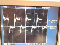
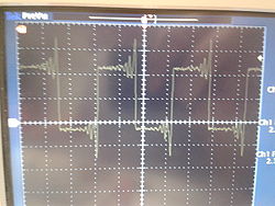
| + | Relevé de l'horloge (PDI CLK) <br> | ||
| + | On observe des oscillations. Ces dernières ont un dépassement de 20%<br> | ||
| + | La fréquence minimale de programmation est de 10 KHZ . Nous sommes à la fréquence de 2 Mhz | ||
| + | <center> | ||
| + | [[Fichier:pfe_p13_clk_pdi.jpg|250px]] | ||
| + | [[Fichier:pfe_p13_clk_pdi2.jpg|250px]] | ||
| + | </center> | ||
| + | |||
| + | =====Données===== | ||
| + | Relevé de la trame de données (PDI DATA) <br> | ||
| + | Fréquence de la trame : 2.7174 Hz <br> | ||
| + | <center>[[Fichier:pfe_p13_pdi_data.jpg |250px]]</center><br> | ||
| + | |||
| + | ===Programmation à l'aide du mkII=== | ||
| + | =====Matériel nécessaire===== | ||
| + | -Pc avec AVR Studio<br> | ||
| + | -Connecteur MKII<br> | ||
| + | -Atxmega<br> | ||
| + | -Led <br> | ||
| + | -Résistance<br><br> | ||
| + | Schéma d'installation : <br> | ||
| + | <center>[[Fichier: pfe_p13_Schéma_test_pdi.JPG|250px]]</center><br><br> | ||
| + | |||
| + | =====AVR Studio===== | ||
| + | Le logiciel AVR Studio est disponible à l'adresse suivante :http://www.atmel.com/microsite/avr_studio_5/ <br> | ||
| + | <center>[[Fichier: pfe_p13_Avr_studio.JPG|500px]]</center><br> | ||
| + | <br> | ||
| + | =====Exemple===== | ||
| + | Clignotement d'une Led :<br> | ||
| + | Code C : <br> | ||
| + | #include <avr/io.h><br> | ||
| + | int main(void)<br> | ||
| + | {<br> | ||
| + | int i;<br> | ||
| + | PORTB_DIR= 0XFF;<br> | ||
| + | while(1)<br> | ||
| + | {<br> | ||
| + | PORTB_OUT= 0x00;<br> | ||
| + | for(i=0;i<=10000;i++);<br> | ||
| + | PORTB_OUT= 0xFF;<br> | ||
| + | for(i=0;i<=10000;i++);<br> | ||
| + | }<br> | ||
| + | }<br> | ||
| + | |||
| + | Relevé du résultat : <br> | ||
| + | <center>[[Fichier:pfe_p13_resultat_prog_pdi.jpg|250px]]</center><br> | ||
| + | |||
| + | ===Programmation via une Raspberry=== | ||
| + | =====Matériel nécessaire===== | ||
| + | Le matériel nécessaire pour programmer les cartes avec une Raspberry est le suivant :<br> | ||
| + | - Pc<br> | ||
| + | - Microcontrôleur : Atxmega par exemple<br> | ||
| + | - Platine d'expérimentation<br> | ||
| + | - Led <br> | ||
| + | - Résistance<br> | ||
| + | |||
| + | =====Bibliothèque===== | ||
| + | Les bibliothèques suivantes sont nécessaire pour reprogrammer en PDI :<br> | ||
| + | - gcc-avr<br> | ||
| + | - binutils-avr<br> | ||
| + | - https://github.com/DiUS/xmega-pdi-pi2 <br> | ||
| + | - build-essential<br> | ||
| + | - g ++ <br> | ||
| + | -libcm2835<br><br> | ||
| + | Installation de la libcm2835<br> | ||
| + | wget http://67.192.60.197/mikem/bcm2835/bcm2835-1.46.tar.gz <br> | ||
| + | tar xvfz bcm2835-1.4.6.tar.gz; <br> | ||
| + | cd bcm2835-1.46; <br> | ||
| + | ./configure; <br> | ||
| + | make; <br> | ||
| + | sudo make install<br><br> | ||
| + | |||
| + | =====Connexion du Pdi sur la Raspbrerry===== | ||
| + | Le PDI sera connecté sur les broches suivantes de la Raspberry :<br> | ||
| + | -broche 1 : 3.3V<br> | ||
| + | -broche 25 : GND <br> | ||
| + | -broche 16 : PDI_Data<br> | ||
| + | -broche 18 : PDI_clk<br> | ||
| + | Correspondance entre les broches et les gpio :<br> | ||
| + | <center>[[Fichier:PFE_P13_Gpio.jpg|500px]]</center> | ||
| + | =====Programmation===== | ||
| + | Un exemple de programmation du microcontrôleur via le PDI | ||
| + | <br><br> | ||
| + | - Compilation du fichier C <br> | ||
| + | $ avr-gcc -g -Os -mmcu=atxmega64a1 -c demo.c <br><br> | ||
| + | - Génération du fichier .hex<br> | ||
| + | $ avr-gcc -g -mmcu=atxmega64a1 -o demo.elf demo.o<br> | ||
| + | $ avr-objcopy -j .text -j .data -O ihex demo.elf demo.hex <br><br> | ||
| + | - Transfert du fichier .hex à la racine de la raspberry<br> | ||
| + | scp nom_fichier.hex pi@adresse_raspberry:~/ <br><br> | ||
| + | - Transfert de la raspberry vers l'atxmega<br> | ||
| + | sudo ./pdi -c (Numéro de la GBIO de la Clock) -d (Numéro de la GBIO de la Data) -a override base address (note: PDI address space) - F Nom du fichier.hex <br> | ||
| + | |||
| + | =====Exemple===== | ||
| + | Clignotement d'une Led :<br> | ||
| + | Code C : <br> | ||
| + | #include <avr/io.h><br> | ||
| + | int main (void)<br> | ||
| + | {<br> | ||
| + | int i;<br> | ||
| + | PORTB.DIR= 1;<br> | ||
| + | while(1)<br> | ||
| + | {<br> | ||
| + | PORTB.OUT=0;<br> | ||
| + | for(i=0;i<=10000;i++);<br> | ||
| + | PORTB.OUT= 1;<br> | ||
| + | for(i=0;i<=10000;i++);<br> | ||
| + | }<br> | ||
| + | }<br> | ||
| + | <br> | ||
| + | Fichier hex généré pour l 'atxmega<br><br> | ||
| + | Extrait du fichier hex :<br> | ||
| + | :1001F0000C94080111241FBECFEFDFE2DEBFCDBF9C | ||
| + | :1002000018BE19BE1ABE1BBE0E940A010C94120130 | ||
| + | :100210000C9400008FEF80932006109224068093A8 | ||
| + | :080220002406FBCFF894FFCF88 | ||
| + | :00000001FF<br><br> | ||
| + | |||
| + | Résultat :<br> | ||
| + | <center>[[Fichier:PFE_p13_PDI_pi2.JPG|250px]]</center> | ||
| + | |||
| + | ===Programmation via un microcontrôleur=== | ||
| + | Le matériel nécessaire pour programmer les cartes avec un microcontrôleur est le suivant :<br> | ||
| + | -2 microcontrôleur de type Atxmega<br> | ||
| + | -Platine d'expérimentation<br> | ||
| + | -Led<br> | ||
| + | -Résistance<br><br> | ||
| + | |||
| + | Schéma de connexion entre les microcontrôleurs :<br> | ||
| + | <center>[[Fichier:Pfe_p13_2atx_connexion.JPG |500px]]</center><br> | ||
| + | <center>'''Cette solutions ne sera pas développée car la Raspberry PI2 possède un nombre nécessaire de GPIO pour pouvoir programmer un noeud'''</center> | ||
| + | |||
| + | == Atmel Software Framework (ASF) == | ||
| + | ====Présentation==== | ||
| + | Extrait issue du site Atmel :<br><br> | ||
| + | The Atmel® Software Framework (ASF) is a MCU software library providing a large collection of embedded software for Atmel flash MCUs: megaAVR, AVR XMEGA, AVR UC3 and SAM devices.<br> | ||
| + | |||
| + | It simplifies the usage of microcontrollers, providing an abstraction to the hardware and high-value middlewares | ||
| + | ASF is designed to be used for evaluation, prototyping, design and production phases | ||
| + | ASF is integrated in the Atmel Studio IDE with a graphical user interface or available as standalone for GCC, IAR compilers | ||
| + | ASF can be downloaded for free<br> | ||
| + | |||
| + | Access the ASF documentation.<br> | ||
| + | |||
| + | Note: ASF in Atmel Studio does not require a specific download. Use Atmel Studio Extension Manager (Tools->Extension Manager) or visit Atmel Gallery to update ASF in Atmel Studio.<br><br> | ||
| + | |||
| + | Le site se situe à l'adresse suivante : [http://asf.atmel.com/docs/latest/ asf framework]<br><br> | ||
| + | Capture d'écran du site :<br> | ||
| + | [[Fichier:Atmel_asf.png|300px|center]] | ||
| + | ====USART==== | ||
| + | =====Format de la trame===== | ||
| + | Le projet P10 souhaite que la trame issue de l'USART soit la suivante :<br><br> | ||
| + | <table border="2" align=center> | ||
| + | <tr> | ||
| + | <td width="250" align=center>Mode de transmission<br> ( S : USART ; U : USB ; R : Radio)</td> | ||
| + | <td width="100" align=center>ID</td> | ||
| + | <td width="100" align=center>Numéro de la <br> carte fille</td> | ||
| + | <td width="100" align=center>Numéro de la <br> carte petite fille</td> | ||
| + | <td width="100" align=center>Data</td> | ||
| + | </tr> | ||
| + | </table> | ||
<br> | <br> | ||
| − | + | Exemple :<br> | |
| + | <table border="2" align=center> | ||
| + | <tr> | ||
| + | <td width="100" align=center>S</td> | ||
| + | <td width="100" align=center>005</td> | ||
| + | <td width="100" align=center>8</td> | ||
| + | <td width="100" align=center>2</td> | ||
| + | <td width="100" align=center>255</td> | ||
| + | </tr> | ||
| + | |||
| + | <tr> | ||
| + | <td width="100" align=center>Data transmise via l'uart</td> | ||
| + | <td width="100" align=center>Noeud 5</td> | ||
| + | <td width="100" align=center>Carte fille 8</td> | ||
| + | <td width="100" align=center>Carte fille 2</td> | ||
| + | <td width="100" align=center>Mesure d'une témperature</td> | ||
| + | </tr> | ||
| + | </table> | ||
| + | <br><br> | ||
| + | |||
| + | =====Implantation===== | ||
| + | [[Fichier: PFE_P13_schema_trame.jpg|center |500 px]] | ||
| + | |||
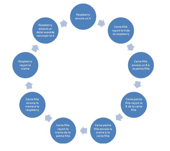
| + | '''Fonctionnement durant la procédure de test''' | ||
| + | [[Fichier: PFE_P13_Fonctionnement_gene_trame.JPG|center |500 px]]<br><br> | ||
| + | '''Commande hub USART (carte A)''' | ||
| + | <table border="2" align=center> | ||
| + | <tr> | ||
| + | <td width="250" align=center >Action</td> | ||
| + | <td width="100" align=center >Envoi</td> | ||
| + | <td width="100" align=center>Reception</td> | ||
| + | </tr> | ||
| + | <tr> | ||
| + | <td width="250" align=center >Récupérer l'ensemble des trames du noeud</td> | ||
| + | <td width="100" align=center >A</td> | ||
| + | <td width="100" align=center> -Trame B<br>-Trame C<br>-Trame D<br>-Trame E<br>-Trame F<br>-Trame G<br>-Trame H<br>-Trame I<br></td> | ||
| + | </tr> | ||
| + | <tr> | ||
| + | <td width="250" align=center colspan="3">Récupération partiel sous réserve de validation</td> | ||
| + | </tr> | ||
| + | <tr> | ||
| + | <td width="250" align=center >Récupérer la trame de la carte B</td> | ||
| + | <td width="100" align=center >B</td> | ||
| + | <td width="100" align=center> Trame B</td> | ||
| + | </tr> | ||
| + | <tr> | ||
| + | <td width="250" align=center >Récupérer la trame de la carte C</td> | ||
| + | <td width="100" align=center >C</td> | ||
| + | <td width="100" align=center> Trame C</td> | ||
| + | </tr> | ||
| + | <tr> | ||
| + | <td width="250" align=center >Récupérer la trame de la carte D</td> | ||
| + | <td width="100" align=center >D</td> | ||
| + | <td width="100" align=center> Trame D</td> | ||
| + | </tr> | ||
| + | <tr> | ||
| + | <td width="250" align=center >Récupérer la trame de la carte E</td> | ||
| + | <td width="100" align=center >E</td> | ||
| + | <td width="100" align=center> Trame E</td> | ||
| + | </tr> | ||
| + | <tr> | ||
| + | <td width="250" align=center >Récupérer la trame de la carte F</td> | ||
| + | <td width="100" align=center >F</td> | ||
| + | <td width="100" align=center> Trame F</td> | ||
| + | </tr> | ||
| + | <tr> | ||
| + | <td width="250" align=center >Récupérer la trame de la carte G</td> | ||
| + | <td width="100" align=center >G</td> | ||
| + | <td width="100" align=center> Trame G</td> | ||
| + | </tr> | ||
| + | <tr> | ||
| + | <td width="250" align=center >Récupérer la trame de la carte H</td> | ||
| + | <td width="100" align=center >H</td> | ||
| + | <td width="100" align=center> Trame H</td> | ||
| + | </tr> | ||
| + | <tr> | ||
| + | <td width="250" align=center >Récupérer la trame de la carte I</td> | ||
| + | <td width="100" align=center >I</td> | ||
| + | <td width="100" align=center> Trame I</td> | ||
| + | </tr> | ||
| + | </table> | ||
| + | <br><br> | ||
| + | |||
| + | =====Génération de trame aléatoire===== | ||
| + | Code : [[Fichier:Generateur_trame_aleatoire.zip|500 px|center]]<br> | ||
| + | Le fichier main (usart_example.c) se trouve dans le dossier suivant :<br> | ||
| + | generateur_trame_aleatoire\USART_EXAMPLE2\src\config\usart_example.c<br><br> | ||
| + | Pour régler la vitesse de l'usb et de l'uart il faut modifier le fichier suivant :<br> | ||
| + | generateur_trame_aleatoire\USART_EXAMPLE2\src\config\conf_usart_example.h<br><br> | ||
| + | Modification de la vitesse pour la liaisons série : #define USART_SERIAL_J1_BAUDRATE 9600<br> | ||
| + | Modification de la vitesse pour la liaisons USB : #define USART_SERIAL_J4_BAUDRATE 115200<br> | ||
| + | |||
| + | <br><br> | ||
| + | [[Fichier:Pfe_p13_courbe_rand.JPG|500 px|center]] | ||
| + | |||
| + | =====Simulation d'une trame donnée===== | ||
| + | Code : [[Fichier:Generateur_trame_donne.zip|500 px|center]]<br> | ||
| + | Le fichier main (usart_example.c) se trouve dans le dossier suivant :<br> | ||
| + | generateur_trame_donne\USART_EXAMPLE2\src\config\usart_example.c<br><br> | ||
| + | Pour régler la vitesse de l'usb et de l'uart il faut modifier le fichier suivant :<br> | ||
| + | generateur_trame_donne\USART_EXAMPLE2\src\config\conf_usart_example.h<br><br> | ||
| + | Modification de la vitesse pour la liaisons série : #define USART_SERIAL_J1_BAUDRATE 9600<br> | ||
| + | Modification de la vitesse pour la liaisons USB : #define USART_SERIAL_J4_BAUDRATE 115200<br> | ||
| + | |||
| + | <br><br> | ||
| + | [[Fichier:Pfe_p13_courbe_temp.JPG |center |500 px]] | ||
| + | <br><br> | ||
| + | [[Fichier:Pfe_p13_courbe_temp2.JPG |center |500 px]] | ||
| + | |||
| + | ====USB==== | ||
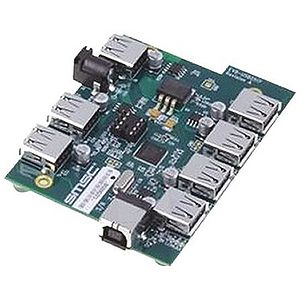
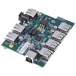
| + | =====Présentation de la board EVB-USB2517===== | ||
<br> | <br> | ||
| − | + | The SMSC USB2517 MultiTRAK™ is a Low-Power Full-Featured High-Speed USB 2.0 compliant hub with seven down-stream ports. The EVB-USB2517 Evaluation Board demonstrates a standalone application for the hub with advanced power saving options and configurable port assignments. It is a demonstration and low-cost evaluation platform that robustly demonstrates the unique features of this device using a low-cost PCB implementation with individual port power control. The EVB-USB2517 is designed for a low cost, power efficient implementation of a High-Speed USB Hub that supports internal default hub configurations as well as optionally supports an external EERPOM configuration. This evaluation platform supports a red LED indicator for the High-Speed hub state as well as standard USB Amber/Green LED indicators for operational state indication. | |
<br> | <br> | ||
| + | Source : Microship<br> | ||
| + | |||
| + | [[Fichier:Pfe_p13_Microchip-EVB-USB2517.jpg|center|300px]] | ||
| + | |||
| + | =====Implantations===== | ||
| + | [[Fichier:Pfe_p13_usb.jpg|center|500 px]] | ||
| + | |||
| + | ==Normalisation électrique== | ||
| + | <table border="2" align=center> | ||
| + | <tr> | ||
| + | <td width="250" align=center >Couleur</td> | ||
| + | <td width="250" align=center >Fonction associée </td> | ||
| + | </tr> | ||
| + | <tr> | ||
| + | <td width="250" align=center >Jaune</td> | ||
| + | <td width="250" align=center >PDI (Data et Clock ) </td> | ||
| + | </tr> | ||
| + | <tr> | ||
| + | <td width="250" align=center >Rouge</td> | ||
| + | <td width="250" align=center >+ 3.3 V </td> | ||
| + | </tr> | ||
| + | <tr> | ||
| + | <td width="250" align=center >Bleu</td> | ||
| + | <td width="250" align=center >Masse </td> | ||
| + | </tr> | ||
| + | <tr> | ||
| + | <td width="250" align=center >Vert/Jaune</td> | ||
| + | <td width="250" align=center >UART </td> | ||
| + | </tr> | ||
| + | </table> | ||
| + | |||
| + | ==Configuration des Raspberry== | ||
| + | ===Raspberry PI=== | ||
| + | Mapping de connection du noeud :<br> | ||
| + | <table border="2" align=center> | ||
| + | <tr> | ||
| + | <td width="250" align=center rowspan="2"></td> | ||
| + | <td width="100" align=center colspan="2">PDI_DATA</td> | ||
| + | <td width="100" align=center colspan="2">PDI_CLOCK</td> | ||
| + | <td width="100" align=center rowspan="2">Action</td> | ||
| + | </tr> | ||
| + | |||
| + | <tr> | ||
| + | <td width="100" align=center>Broche</td> | ||
| + | <td width="100" align=center>Gpio</td> | ||
| + | <td width="100" align=center>Broche</td> | ||
| + | <td width="100" align=center>Gpio</td> | ||
| + | </tr> | ||
| + | <tr> | ||
| + | <td width="100" align=center>Carte A (Hub USART)</td> | ||
| + | <td width="100" align=center>16</td> | ||
| + | <td width="100" align=center>23</td> | ||
| + | <td width="100" align=center>18</td> | ||
| + | <td width="100" align=center>24</td> | ||
| + | <td width="250" align=center>Reprogrammez le HUB USART en pdi<br> Il faut désactiver l'interface SPI de la raspberry</td> | ||
| + | </tr> | ||
| + | <tr> | ||
| + | <td width="100" align=center>Carte fille B (1)</td> | ||
| + | <td width="100" align=center>15</td> | ||
| + | <td width="100" align=center>22</td> | ||
| + | <td width="100" align=center>13</td> | ||
| + | <td width="100" align=center>27</td> | ||
| + | <td width="250" align=center>Reprogrammez la carte fille B en pdi</td> | ||
| + | </tr> | ||
| + | <tr> | ||
| + | <td width="100" align=center>Carte fille C (2)</td> | ||
| + | <td width="100" align=center>19</td> | ||
| + | <td width="100" align=center>10</td> | ||
| + | <td width="100" align=center>21</td> | ||
| + | <td width="100" align=center>9</td> | ||
| + | <td width="250" align=center>Reprogrammez la carte fille C en pdi</td> | ||
| + | </tr> | ||
| + | <tr> | ||
| + | <td width="100" align=center>Carte fille D (3)</td> | ||
| + | <td width="100" align=center>11</td> | ||
| + | <td width="100" align=center>17</td> | ||
| + | <td width="100" align=center>12</td> | ||
| + | <td width="100" align=center>18</td> | ||
| + | <td width="250" align=center>Reprogrammez la carte fille D en pdi</td> | ||
| + | </tr> | ||
| + | <tr> | ||
| + | <td width="100" align=center>Carte fille E (4)</td> | ||
| + | <td width="100" align=center>7</td> | ||
| + | <td width="100" align=center>4</td> | ||
| + | <td width="100" align=center>22</td> | ||
| + | <td width="100" align=center>25</td> | ||
| + | <td width="250" align=center>Reprogrammez la carte fille E en pdi</td> | ||
| + | </tr> | ||
| + | </table> | ||
| + | <br><br> | ||
| + | <center>[[Fichier:PFE_P13_Raspberry-pi-gpio.jpg |500 px]]</center> | ||
| + | |||
| + | ===Raspberry PI 2=== | ||
| + | <table border="2" align=center> | ||
| + | <tr> | ||
| + | <td width="250" align=center rowspan="2"></td> | ||
| + | <td width="100" align=center colspan="2">PDI_DATA</td> | ||
| + | <td width="100" align=center colspan="2">PDI_CLOCK</td> | ||
| + | <td width="100" align=center rowspan="2">Action</td> | ||
| + | </tr> | ||
| + | |||
| + | <tr> | ||
| + | <td width="100" align=center>Broche</td> | ||
| + | <td width="100" align=center>Gpio</td> | ||
| + | <td width="100" align=center>Broche</td> | ||
| + | <td width="100" align=center>Gpio</td> | ||
| + | </tr> | ||
| + | |||
| + | <tr> | ||
| + | <td width="100" align=center>Carte A (Hub USART)</td> | ||
| + | <td width="100" align=center>11</td> | ||
| + | <td width="100" align=center>17</td> | ||
| + | <td width="100" align=center>13</td> | ||
| + | <td width="100" align=center>27</td> | ||
| + | <td width="250" align=center>Reprogrammez le HUB USART en pdi<br> Il faut désactiver l'interface SPI de la raspberry</td> | ||
| + | </tr> | ||
| + | <tr> | ||
| + | <td width="100" align=center>Carte fille B(1)</td> | ||
| + | <td width="100" align=center>12</td> | ||
| + | <td width="100" align=center>18</td> | ||
| + | <td width="100" align=center>22</td> | ||
| + | <td width="100" align=center>25</td> | ||
| + | <td width="250" align=center>Reprogrammez la carte fille B en pdi</td> | ||
| + | </tr> | ||
| + | <tr> | ||
| + | <td width="100" align=center>Carte fille C (2)</td> | ||
| + | <td width="100" align=center>33</td> | ||
| + | <td width="100" align=center>13</td> | ||
| + | <td width="100" align=center>35</td> | ||
| + | <td width="100" align=center>19</td> | ||
| + | <td width="250" align=center>Reprogrammez la carte fille C en pdi</td> | ||
| + | </tr> | ||
| + | <tr> | ||
| + | <td width="100" align=center>Carte fille D (3)</td> | ||
| + | <td width="100" align=center>16</td> | ||
| + | <td width="100" align=center>23</td> | ||
| + | <td width="100" align=center>18</td> | ||
| + | <td width="100" align=center>24</td> | ||
| + | <td width="250" align=center>Reprogrammez la carte fille D en pdi</td> | ||
| + | </tr> | ||
| + | <tr> | ||
| + | <td width="100" align=center>Carte fille E (4)</td> | ||
| + | <td width="100" align=center>36</td> | ||
| + | <td width="100" align=center>16</td> | ||
| + | <td width="100" align=center>38</td> | ||
| + | <td width="100" align=center>20</td> | ||
| + | <td width="250" align=center>Reprogrammez la carte fille E en pdi</td> | ||
| + | </tr> | ||
| + | <tr> | ||
| + | <td width="100" align=center>Carte fille F (5)</td> | ||
| + | <td width="100" align=center>15</td> | ||
| + | <td width="100" align=center>22</td> | ||
| + | <td width="100" align=center>37</td> | ||
| + | <td width="100" align=center>26</td> | ||
| + | <td width="250" align=center>Reprogrammez la carte fille F en pdi</td> | ||
| + | </tr> | ||
| + | <tr> | ||
| + | <td width="100" align=center>Carte fille G (6)</td> | ||
| + | <td width="100" align=center>32</td> | ||
| + | <td width="100" align=center>12</td> | ||
| + | <td width="100" align=center>40</td> | ||
| + | <td width="100" align=center>21</td> | ||
| + | <td width="250" align=center>Reprogrammez la carte fille G en pdi</td> | ||
| + | </tr> | ||
| + | <tr> | ||
| + | <td width="100" align=center>Carte fille H (7)</td> | ||
| + | <td width="100" align=center>19</td> | ||
| + | <td width="100" align=center>10</td> | ||
| + | <td width="100" align=center>21</td> | ||
| + | <td width="100" align=center>9</td> | ||
| + | <td width="250" align=center>Reprogrammez la carte fille H en pdi</td> | ||
| + | </tr> | ||
| + | <tr> | ||
| + | <td width="100" align=center>Carte fille I (8)</td> | ||
| + | <td width="100" align=center>29</td> | ||
| + | <td width="100" align=center>5</td> | ||
| + | <td width="100" align=center>31</td> | ||
| + | <td width="100" align=center>6</td> | ||
| + | <td width="250" align=center>Reprogrammez la carte fille I en pdi</td> | ||
| + | </tr> | ||
| + | </table><br> | ||
| + | <center>[[Fichier:PFE_P13_Gpio-raspberry_pi_2.jpg]]</center> | ||
| + | |||
| + | ==Exemple de capteur== | ||
| + | ===Mesure de la température=== | ||
| + | |||
| + | Ce type de capteur utilise le convertisseur analogique numérique du microcontroleur. Les paramétres à configurés seront les suivantes :<br> | ||
| + | * Quantum<br> | ||
| + | * Plage de mesure<br> | ||
| + | * Registre <br><br> | ||
| + | |||
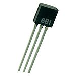
| + | [[Fichier:Pfe_p13-capteur-temp.jpg|150px|center]]<br> | ||
| + | Ce capteur à les caractéristiques suivantes :<br> | ||
| + | Fournisseur : Conrard<br> | ||
| + | Référence :Capteur de température numérique TSIC506 boîtier TO 92 B & B Thermotechnik TSIC506-TO92<br> | ||
| + | Plage de mesure :-10 C - 60C<br> | ||
| + | Tension d'alimentation :3-5.5V<br> | ||
| + | Précision : +/- 0.1 C<br> | ||
| + | Consommation : 30 - 60 µA<br> | ||
| + | <br><br> | ||
| + | '''Implantation'''<br> | ||
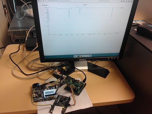
| + | Les cartes Xplained mise à notre disposition sont équipées de capteur de température.Nous avons implanté un pseudo noeud de capteur dans la salle E306 le 1 février<br> | ||
| + | Code : [[Fichier:Capteur_temperature.zip|500 px|center]]<br> | ||
| + | Le fichier main (adc_example1_gfx.c) se trouve dans le dossier suivant :<br> | ||
| + | capteur_temperature\src\adc_example1_gfx.c<br><br> | ||
| + | Pour régler la vitesse de l'usb et de l'uart il faut modifier le fichier suivant :<br> | ||
| + | capteur_temperature\src\config\conf_usart_spi.h<br><br> | ||
| + | Modification de la vitesse pour la liaisons série : #define USART_SERIAL_J1_BAUDRATE 9600<br> | ||
| + | Modification de la vitesse pour la liaisons USB : #define USART_SERIAL_J4_BAUDRATE 115200<br> | ||
| + | |||
| + | <br><br> | ||
| + | [[Fichier:PFE_P13_implantation-temp.jpg|500px|center]]<br> | ||
| + | |||
| + | ===Mesure du volume sonore=== | ||
| + | |||
| + | La mesure d'un volume sonore se réalise par la transformation d'un vibration en un signal éléctrique.Afin de pouvoir l'exploiter il faudra | ||
| + | le connecté sur le convertisseur analogique numérique du microcontroleur.Les paramétres à configurés seront les suivantes :<br> | ||
| + | * Quantum<br> | ||
| + | * Registre <br><br> | ||
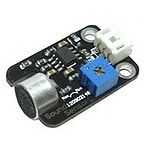
| + | [[Fichier:Pfe_p13-capteur-son.jpg|150px|center]] | ||
| + | Ce capteur à les caractéristiques suivantes :<br> | ||
| + | Fournisseur : Zartronic.fr<br> | ||
| + | Référence :Capteur Sonore Analogique<br> | ||
| + | Tension d'alimentation :5V<br> | ||
| + | <br><br> | ||
| + | Exemple de courbe généré par le générateur de trame <br><br> | ||
| + | [[Fichier:Pfe_p13_courbe_son.JPG|500px|center]] | ||
| + | |||
| + | ===Mesure de la luminosité=== | ||
| + | |||
| + | La mesure de la luminosité s'effectue avec l'aide d'un photo-transistor. Le photo-tansistor fera varier une résistance. On peut mesurer sa tension | ||
| + | a ses bornes. Cette tension étant trés faible il est nécessaire d'avoir un amplificateur en sortie. La tension sera exploitable par le | ||
| + | convertisseur analogique numérique du microcontroleur.Les paramétres à configurés seront les suivantes :<br> | ||
| + | * Quantum<br> | ||
| + | * Registre <br><br> | ||
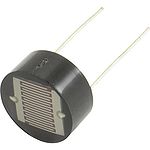
| + | [[Fichier:Pfe_p13-capteur-luminosite.jpg|150px|center]] | ||
| + | Ce capteur à les caractéristiques suivantes :<br> | ||
| + | Fournisseur : Conrard<br> | ||
| + | Référence :Photo-résistance FW200<br> | ||
| + | <br><br> | ||
| + | |||
| + | ==Composition d'un noeud== | ||
| + | ====La carte mère==== | ||
| + | '''Composition'''<br> | ||
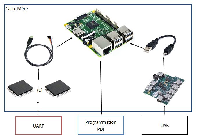
| + | La carte mère est constitué de :<br> | ||
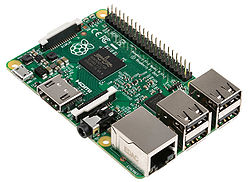
| + | - une carte raspberry pi<br> | ||
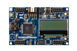
| + | - un hub USART (matérialisé ici par une carte XMega-A3BUX Xplained)<br> | ||
| + | - un hub USB <br> | ||
| + | <table border="1" align=center> | ||
| + | <tr align=center> | ||
| + | <td colspan="3">Amont (Réseaux)</td> | ||
| + | </tr> | ||
| + | <tr align=center> | ||
| + | <td>Hub UART</td> | ||
| + | <td>Rapsberry</td> | ||
| + | <td>Hub USB</td> | ||
| + | |||
| + | </tr> | ||
| + | <tr align=center> | ||
| + | <td>[[Fichier:AVR_XMEGAA3BU_Xplained.jpg |250px|center]]</td> | ||
| + | <td>[[Fichier:Raspberry-pi-2.jpg|250 px |center]]</td> | ||
| + | <td> [[Fichier:Pfe_p13_Microchip-EVB-USB2517.jpg |250 px |center]] | ||
| + | </td> | ||
| + | |||
| + | </tr> | ||
| + | <tr align=center> | ||
| + | <td colspan="3">Aval (Vers carte fille)</td> | ||
| + | </tr> | ||
| + | |||
| + | </table> | ||
| + | |||
| + | '''Fonctions'''<br> | ||
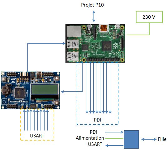
| + | <center>[[Fichier:PFE_P13_Fonction_carte_mère.JPG|500px]]</center> | ||
| + | <br> | ||
| + | |||
| + | '''Connexions'''<br> | ||
| + | <table border="2" align=center> | ||
| + | <tr> | ||
| + | <td width="250" align=center >Ancienne appellation </td> | ||
| + | <td width="100" align=center >Nouvelle appellation</td> | ||
| + | </tr> | ||
| + | <tr> | ||
| + | <td width="250" align=center >Carte fille 1 </td> | ||
| + | <td width="100" align=center >Carte B</td> | ||
| + | </tr> | ||
| + | <tr> | ||
| + | <td width="250" align=center >Carte fille 2 </td> | ||
| + | <td width="100" align=center >Carte C</td> | ||
| + | </tr> | ||
| + | <tr> | ||
| + | <td width="250" align=center >Carte fille 3 </td> | ||
| + | <td width="250" align=center >Carte D</td> | ||
| + | </tr> | ||
| + | <tr> | ||
| + | <td width="250" align=center >Carte fille 4 </td> | ||
| + | <td width="100" align=center >Carte E</td> | ||
| + | </tr> | ||
| + | <tr> | ||
| + | <td width="250" align=center >Carte fille 5 </td> | ||
| + | <td width="100" align=center >Carte F</td> | ||
| + | </tr> | ||
| + | <tr> | ||
| + | <td width="250" align=center >Carte fille 6 </td> | ||
| + | <td width="100" align=center >Carte G</td> | ||
| + | </tr> | ||
| + | <tr> | ||
| + | <td width="250" align=center >Carte fille 7 </td> | ||
| + | <td width="100" align=center >Carte H</td> | ||
| + | </tr> | ||
| + | <tr> | ||
| + | <td width="250" align=center >Carte fille 8 </td> | ||
| + | <td width="100" align=center >Carte I</td> | ||
| + | </tr> | ||
| + | </table> | ||
| + | |||
| + | ====La carte fille==== | ||
| + | '''Composition'''<br> | ||
| + | La carte fille est constituée d'une carte Xplained<br> | ||
| + | <table border="1" align="center"> | ||
| + | <tr align="center"><td>Amont (Vers Raspberry )</td></tr> | ||
| + | <tr align="center"><td>[[Fichier:AVR_XMEGAA3BU_Xplained.jpg |250px|center]]</td></tr> | ||
| + | <tr align="center"><td>Aval (Vers carte petite fille) </td></tr> | ||
| + | </table> | ||
| + | |||
| + | '''Fonction'''<br> | ||
| + | Les fonctions de la carte sont : | ||
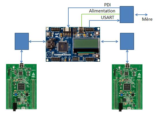
| + | <center>[[Fichier:Pfe_p13_carte_fille_fonction.JPG]]</center> | ||
| + | |||
| + | '''Connexion''' <br> | ||
| + | <table border="2" align=center> | ||
| + | <tr> | ||
| + | <td width="100" align=center rowspan="3"> </td> | ||
| + | <td width="250" align=center colspan="4" >Données</td> | ||
| + | <td width="250" align=center colspan="4">Programmation</td> | ||
| + | </tr> | ||
| + | <tr> | ||
| + | <td width="250" align=center colspan="2">USART</td> | ||
| + | <td width="250" align=center colspan="2">USB</td> | ||
| + | <td width="250" align=center colspan="2">PDI</td> | ||
| + | <td width="250" align=center colspan="2">SPI / I2C ...</td> | ||
| + | </tr> | ||
| + | <tr> | ||
| + | <td width="100" align=center >Amont<br> (vers la raspberry)</td> | ||
| + | <td width="100" align=center >Aval <br>(vers les capteurs)</td> | ||
| + | <td width="100" align=center >Amont<br> (vers la raspberry)</td> | ||
| + | <td width="100" align=center >Aval <br>(vers les capteurs)</td> | ||
| + | <td width="100" align=center >Amont <br>(vers la raspberry)</td> | ||
| + | <td width="100" align=center >Aval <br>(vers les capteurs)</td> | ||
| + | <td width="100" align=center >Amont <br>(vers la raspberry)</td> | ||
| + | <td width="100" align=center >Aval <br>(vers les capteurs)</td> | ||
| + | </tr> | ||
| + | <tr> | ||
| + | <td width="100" align=center >Carte B</td> | ||
| + | <td width="100" align=center >Carte A <br>(Interface ttyUSB0)</td> | ||
| + | <td width="100" align=center >- Carte B1<br>- Carte B2</td> | ||
| + | <td width="100" align=center >Hub USB <br>(Interface ttyACM0)</td> | ||
| + | <td width="100" align=center >-</td> | ||
| + | <td width="100" align=center >Carte mère <br>(Voir configuration Rasbperry)</td> | ||
| + | <td width="100" align=center >-</td> | ||
| + | <td width="100" align=center >-</td> | ||
| + | <td width="100" align=center >- Carte B1<br>- Carte B2</td> | ||
| + | </tr> | ||
| + | <tr> | ||
| + | <td width="100" align=center >Carte C</td> | ||
| + | <td width="100" align=center >Carte A <br>(Interface ttyUSB1)</td> | ||
| + | <td width="100" align=center >- Carte C1<br>- Carte C2</td> | ||
| + | <td width="100" align=center >Hub USB <br>(Interface ttyACM1)</td> | ||
| + | <td width="100" align=center >-</td> | ||
| + | <td width="100" align=center >Carte mère <br>(Voir configuration Rasbperry)</td> | ||
| + | <td width="100" align=center >-</td> | ||
| + | <td width="100" align=center >-</td> | ||
| + | <td width="100" align=center >- Carte C1<br>- Carte C2</td> | ||
| + | </tr> | ||
| + | <tr> | ||
| + | <td width="100" align=center >Carte D</td> | ||
| + | <td width="100" align=center >Carte A<br>(Interface ttyUSB2)</td> | ||
| + | <td width="100" align=center >- Carte D1<br>- Carte D2</td> | ||
| + | <td width="100" align=center >Hub USB <br>(Interface ttyACM2)</td> | ||
| + | <td width="100" align=center >-</td> | ||
| + | <td width="100" align=center >Carte mère <br>(Voir configuration Rasbperry)</td> | ||
| + | <td width="100" align=center >-</td> | ||
| + | <td width="100" align=center >-</td> | ||
| + | <td width="100" align=center >- Carte D1<br>- Carte D2</td> | ||
| + | </tr> | ||
| + | <tr> | ||
| + | <td width="100" align=center >Carte E</td> | ||
| + | <td width="100" align=center >Carte A <br>(Interface ttyUSB3)</td> | ||
| + | <td width="100" align=center >- Carte E1<br>- Carte E2</td> | ||
| + | <td width="100" align=center >Hub USB <br>(Interface ttyACM3)</td> | ||
| + | <td width="100" align=center >-</td> | ||
| + | <td width="100" align=center >Carte mère <br>(Voir configuration Rasbperry)</td> | ||
| + | <td width="100" align=center >-</td> | ||
| + | <td width="100" align=center >-</td> | ||
| + | <td width="100" align=center >- Carte E1<br>- Carte E2</td> | ||
| + | </tr> | ||
| + | <tr> | ||
| + | <td width="100" align=center >Carte F</td> | ||
| + | <td width="100" align=center >Carte A<br>(Interface ttyUSB4)</td> | ||
| + | <td width="100" align=center >- Carte F1<br>- Carte F2</td> | ||
| + | <td width="100" align=center >Hub USB <br>(Interface ttyACM4)</td> | ||
| + | <td width="100" align=center >-</td> | ||
| + | <td width="100" align=center >Carte mère <br>(Voir configuration Rasbperry)</td> | ||
| + | <td width="100" align=center >-</td> | ||
| + | <td width="100" align=center >-</td> | ||
| + | <td width="100" align=center >- Carte F1<br>- Carte F2</td> | ||
| + | </tr> | ||
| + | <tr> | ||
| + | <td width="100" align=center >Carte G</td> | ||
| + | <td width="100" align=center >Carte A<br>(Interface ttyUSB5)</td> | ||
| + | <td width="100" align=center >- Carte G1<br>- Carte G2</td> | ||
| + | <td width="100" align=center >Hub USB <br>(Interface ttyACM5)</td> | ||
| + | <td width="100" align=center >-</td> | ||
| + | <td width="100" align=center >Carte mère <br>(Voir configuration Rasbperry)</td> | ||
| + | <td width="100" align=center >-</td> | ||
| + | <td width="100" align=center >-</td> | ||
| + | <td width="100" align=center >- Carte G1<br>- Carte G2</td> | ||
| + | </tr> | ||
| + | <tr> | ||
| + | <td width="100" align=center >Carte H</td> | ||
| + | <td width="100" align=center >Carte A<br>(Interface ttyUSB6)</td> | ||
| + | <td width="100" align=center >- Carte H1<br>- Carte H2</td> | ||
| + | <td width="100" align=center >Hub USB <br>(Interface ttyACM6)</td> | ||
| + | <td width="100" align=center >-</td> | ||
| + | <td width="100" align=center >Carte mère <br>(Voir configuration Rasbperry)</td> | ||
| + | <td width="100" align=center >-</td> | ||
| + | <td width="100" align=center >-</td> | ||
| + | <td width="100" align=center >- Carte H1<br>- Carte H2</td> | ||
| + | </tr> | ||
| + | <tr> | ||
| + | <td width="100" align=center >Carte I</td> | ||
| + | <td width="100" align=center >Carte A<br>(Interface ttyUSB7)</td> | ||
| + | <td width="100" align=center >- Carte I1<br>- Carte I2</td> | ||
| + | <td width="100" align=center >Hub USB <br>(Interface ttyACM7)</td> | ||
| + | <td width="100" align=center >-</td> | ||
| + | <td width="100" align=center >Carte mère <br>(Voir configuration Rasbperry)</td> | ||
| + | <td width="100" align=center >-</td> | ||
| + | <td width="100" align=center >-</td> | ||
| + | <td width="100" align=center >- Carte I1<br>- Carte I2</td> | ||
| + | </tr> | ||
| + | </table> | ||
| + | |||
| + | ====La carte petite fille==== | ||
| + | '''Présentation'''<br> | ||
| + | Cette carte ne sera pas présente dans le nœud. Le générateur de trame nous simulera les informations remontées par cette dernière .<br> | ||
| + | '''Fonction'''<br> | ||
| + | <center>[[Fichier:Pfe_p13_carte_petite_fille_fonction.JPG]]</center> | ||
| + | '''Connexion'''<br> | ||
| + | Dénomination des cartes :<br> | ||
| + | <table border="2" align=center> | ||
| + | <tr> | ||
| + | <td width="250" align=center >Carte parent </td> | ||
| + | <td width="250" align=center >Ancienne appellation </td> | ||
| + | <td width="100" align=center >Nouvelle appellation</td> | ||
| + | </tr> | ||
| + | <tr> | ||
| + | <td width="100" align=center rowspan="2">Carte B (Ex carte fille 1)</td> | ||
| + | <td width="250" align=center >Carte Petite fille 1 </td> | ||
| + | <td width="100" align=center >Carte B1</td> | ||
| + | </tr> | ||
| + | <tr> | ||
| + | <td width="250" align=center >Carte Petite fille 2 </td> | ||
| + | <td width="100" align=center >Carte B2</td> | ||
| + | </tr> | ||
| + | <tr> | ||
| + | <td width="100" align=center rowspan="2">Carte C (Ex carte fille 2)</td> | ||
| + | <td width="250" align=center >Carte Petite fille 1 </td> | ||
| + | <td width="100" align=center >Carte C1</td> | ||
| + | </tr> | ||
| + | <tr> | ||
| + | <td width="250" align=center >Carte Petite fille 2 </td> | ||
| + | <td width="100" align=center >Carte C2</td> | ||
| + | </tr> | ||
| + | <tr> | ||
| + | <td width="100" align=center rowspan="2">Carte D (Ex carte fille 3)</td> | ||
| + | <td width="250" align=center >Carte Petite fille 1 </td> | ||
| + | <td width="100" align=center >Carte D1</td> | ||
| + | </tr> | ||
| + | <tr> | ||
| + | <td width="250" align=center >Carte Petite fille 2 </td> | ||
| + | <td width="100" align=center >Carte D2</td> | ||
| + | </tr> | ||
| + | <tr> | ||
| + | <td width="100" align=center rowspan="2">Carte E (Ex carte fille 4)</td> | ||
| + | <td width="250" align=center >Carte Petite fille 1 </td> | ||
| + | <td width="100" align=center >Carte E1</td> | ||
| + | </tr> | ||
| + | <tr> | ||
| + | <td width="250" align=center >Carte Petite fille 2 </td> | ||
| + | <td width="100" align=center >Carte E2</td> | ||
| + | </tr> | ||
| + | <tr> | ||
| + | <td width="100" align=center rowspan="2">Carte F(Ex carte fille 5)</td> | ||
| + | <td width="250" align=center >Carte Petite fille 1 </td> | ||
| + | <td width="100" align=center >Carte F1</td> | ||
| + | </tr> | ||
| + | <tr> | ||
| + | <td width="250" align=center >Carte Petite fille 2 </td> | ||
| + | <td width="100" align=center >Carte F2</td> | ||
| + | </tr> | ||
| + | <tr> | ||
| + | <td width="100" align=center rowspan="2">Carte G (Ex carte fille 6)</td> | ||
| + | <td width="250" align=center >Carte Petite fille 1 </td> | ||
| + | <td width="100" align=center >Carte G1</td> | ||
| + | </tr> | ||
| + | <tr> | ||
| + | <td width="250" align=center >Carte Petite fille 2 </td> | ||
| + | <td width="100" align=center >Carte G2</td> | ||
| + | </tr> | ||
| + | <tr> | ||
| + | <td width="100" align=center rowspan="2">Carte H (Ex carte fille 7)</td> | ||
| + | <td width="250" align=center >Carte Petite fille 1 </td> | ||
| + | <td width="100" align=center >Carte H1</td> | ||
| + | </tr> | ||
| + | <tr> | ||
| + | <td width="250" align=center >Carte Petite fille 2 </td> | ||
| + | <td width="100" align=center >Carte H2</td> | ||
| + | </tr> | ||
| + | <tr> | ||
| + | <td width="100" align=center rowspan="2">Carte I (Ex carte fille 8)</td> | ||
| + | <td width="250" align=center >Carte Petite fille 1 </td> | ||
| + | <td width="100" align=center >Carte I1</td> | ||
| + | </tr> | ||
| + | <tr> | ||
| + | <td width="250" align=center >Carte Petite fille 2 </td> | ||
| + | <td width="100" align=center >Carte I2</td> | ||
| + | </tr> | ||
| + | </table> | ||
| + | <br><br> | ||
| + | |||
| + | <table border="2" align=center> | ||
| + | <tr> | ||
| + | <td width="100" align=center rowspan="3"> </td> | ||
| + | <td width="250" align=center colspan="5" >Données</td> | ||
| + | <td width="250" align=center colspan="4">Programmation</td> | ||
| + | </tr> | ||
| + | <tr> | ||
| + | <td width="250" align=center colspan="2">USART</td> | ||
| + | <td width="250" align=center colspan="2">USB</td> | ||
| + | <td width="100" align=center rowspan="2" >Type<br> de données</td> | ||
| + | <td width="250" align=center colspan="2">PDI</td> | ||
| + | <td width="250" align=center colspan="2">SPI / I2C ...</td> | ||
| + | </tr> | ||
| + | <tr> | ||
| + | <td width="100" align=center >Amont<br> (vers la raspberry)</td> | ||
| + | <td width="100" align=center >Aval <br>(vers les capteurs)</td> | ||
| + | |||
| + | <td width="100" align=center >Amont<br> (vers la raspberry)</td> | ||
| + | <td width="100" align=center >Aval <br>(vers les capteurs)</td> | ||
| + | <td width="100" align=center >Amont <br>(vers la raspberry)</td> | ||
| + | <td width="100" align=center >Aval <br>(vers les capteurs)</td> | ||
| + | <td width="100" align=center >Amont <br>(vers la raspberry)</td> | ||
| + | <td width="100" align=center >Aval <br>(vers les capteurs)</td> | ||
| + | </tr> | ||
| + | <tr> | ||
| + | <td width="100" align=center >Carte B1</td> | ||
| + | <td width="100" align=center >Carte B </td> | ||
| + | <td width="100" align=center >-</td> | ||
| + | <td width="100" align=center >Carte B</td> | ||
| + | <td width="100" align=center >-</td> | ||
| + | <td width="100" align=center >Température</td> | ||
| + | <td width="100" align=center >-</td> | ||
| + | <td width="100" align=center >-</td> | ||
| + | <td width="100" align=center >Carte B</td> | ||
| + | <td width="100" align=center >-</td> | ||
| + | </tr> | ||
| + | <tr> | ||
| + | <td width="100" align=center >Carte B2</td> | ||
| + | <td width="100" align=center >Carte B </td> | ||
| + | <td width="100" align=center >-</td> | ||
| + | <td width="100" align=center >Carte B</td> | ||
| + | <td width="100" align=center >-</td> | ||
| + | <td width="100" align=center ></td> | ||
| + | <td width="100" align=center >-</td> | ||
| + | <td width="100" align=center >-</td> | ||
| + | <td width="100" align=center >Carte B</td> | ||
| + | <td width="100" align=center >-</td> | ||
| + | </tr> | ||
| + | <tr> | ||
| + | <td width="100" align=center >Carte C1</td> | ||
| + | <td width="100" align=center >Carte C </td> | ||
| + | <td width="100" align=center >-</td> | ||
| + | <td width="100" align=center >Carte C</td> | ||
| + | <td width="100" align=center >-</td> | ||
| + | <td width="100" align=center >Température</td> | ||
| + | <td width="100" align=center >-</td> | ||
| + | <td width="100" align=center >-</td> | ||
| + | <td width="100" align=center >Carte C</td> | ||
| + | <td width="100" align=center >-</td> | ||
| + | </tr> | ||
| + | <tr> | ||
| + | <td width="100" align=center >Carte C2</td> | ||
| + | <td width="100" align=center >Carte C </td> | ||
| + | <td width="100" align=center >-</td> | ||
| + | <td width="100" align=center >Carte C</td> | ||
| + | <td width="100" align=center >-</td> | ||
| + | <td width="100" align=center ></td> | ||
| + | <td width="100" align=center >-</td> | ||
| + | <td width="100" align=center >-</td> | ||
| + | <td width="100" align=center >Carte C</td> | ||
| + | <td width="100" align=center >-</td> | ||
| + | </tr> | ||
| + | <tr> | ||
| + | <td width="100" align=center >Carte D1</td> | ||
| + | <td width="100" align=center >Carte D </td> | ||
| + | <td width="100" align=center >-</td> | ||
| + | <td width="100" align=center >Carte C</td> | ||
| + | <td width="100" align=center >-</td> | ||
| + | <td width="100" align=center ></td> | ||
| + | <td width="100" align=center >-</td> | ||
| + | <td width="100" align=center >-</td> | ||
| + | <td width="100" align=center >Carte D</td> | ||
| + | <td width="100" align=center >-</td> | ||
| + | </tr> | ||
| + | <tr> | ||
| + | <td width="100" align=center >Carte D2</td> | ||
| + | <td width="100" align=center >Carte D </td> | ||
| + | <td width="100" align=center >-</td> | ||
| + | <td width="100" align=center >Carte C</td> | ||
| + | <td width="100" align=center >-</td> | ||
| + | <td width="100" align=center ></td> | ||
| + | <td width="100" align=center >-</td> | ||
| + | <td width="100" align=center >-</td> | ||
| + | <td width="100" align=center >Carte D</td> | ||
| + | <td width="100" align=center >-</td> | ||
| + | </tr> | ||
| + | <tr> | ||
| + | <td width="100" align=center >Carte E1</td> | ||
| + | <td width="100" align=center >Carte E </td> | ||
| + | <td width="100" align=center >-</td> | ||
| + | <td width="100" align=center >Carte E</td> | ||
| + | <td width="100" align=center >-</td> | ||
| + | <td width="100" align=center ></td> | ||
| + | <td width="100" align=center >-</td> | ||
| + | <td width="100" align=center >-</td> | ||
| + | <td width="100" align=center >Carte E</td> | ||
| + | <td width="100" align=center >-</td> | ||
| + | </tr> | ||
| + | <tr> | ||
| + | <td width="100" align=center >Carte E2</td> | ||
| + | <td width="100" align=center >Carte E </td> | ||
| + | <td width="100" align=center >-</td> | ||
| + | <td width="100" align=center >Carte E</td> | ||
| + | <td width="100" align=center >-</td> | ||
| + | <td width="100" align=center ></td> | ||
| + | <td width="100" align=center >-</td> | ||
| + | <td width="100" align=center >-</td> | ||
| + | <td width="100" align=center >Carte E</td> | ||
| + | <td width="100" align=center >-</td> | ||
| + | </tr> | ||
| + | <tr> | ||
| + | <td width="100" align=center >Carte F1</td> | ||
| + | <td width="100" align=center >Carte F </td> | ||
| + | <td width="100" align=center >-</td> | ||
| + | <td width="100" align=center >Carte F</td> | ||
| + | <td width="100" align=center >-</td> | ||
| + | <td width="100" align=center ></td> | ||
| + | <td width="100" align=center >-</td> | ||
| + | <td width="100" align=center >-</td> | ||
| + | <td width="100" align=center >Carte F</td> | ||
| + | <td width="100" align=center >-</td> | ||
| + | </tr> | ||
| + | <tr> | ||
| + | <td width="100" align=center >Carte F2</td> | ||
| + | <td width="100" align=center >Carte F </td> | ||
| + | <td width="100" align=center >-</td> | ||
| + | <td width="100" align=center >Carte F</td> | ||
| + | <td width="100" align=center >-</td> | ||
| + | <td width="100" align=center ></td> | ||
| + | <td width="100" align=center >-</td> | ||
| + | <td width="100" align=center >-</td> | ||
| + | <td width="100" align=center >Carte F</td> | ||
| + | <td width="100" align=center >-</td> | ||
| + | </tr> | ||
| + | |||
| + | <tr> | ||
| + | <td width="100" align=center >Carte G1</td> | ||
| + | <td width="100" align=center >Carte G </td> | ||
| + | <td width="100" align=center >-</td> | ||
| + | <td width="100" align=center >Carte G</td> | ||
| + | <td width="100" align=center >-</td> | ||
| + | <td width="100" align=center ></td> | ||
| + | <td width="100" align=center >-</td> | ||
| + | <td width="100" align=center >-</td> | ||
| + | <td width="100" align=center >Carte G</td> | ||
| + | <td width="100" align=center >-</td> | ||
| + | </tr> | ||
| + | <tr> | ||
| + | <td width="100" align=center >Carte G2</td> | ||
| + | <td width="100" align=center >Carte G </td> | ||
| + | <td width="100" align=center >-</td> | ||
| + | <td width="100" align=center >Carte G</td> | ||
| + | <td width="100" align=center >-</td> | ||
| + | <td width="100" align=center ></td> | ||
| + | <td width="100" align=center >-</td> | ||
| + | <td width="100" align=center >-</td> | ||
| + | <td width="100" align=center >Carte G</td> | ||
| + | <td width="100" align=center >-</td> | ||
| + | </tr> | ||
| + | |||
| + | <tr> | ||
| + | <td width="100" align=center >Carte H1</td> | ||
| + | <td width="100" align=center >Carte H </td> | ||
| + | <td width="100" align=center >-</td> | ||
| + | <td width="100" align=center >Carte H</td> | ||
| + | <td width="100" align=center >-</td> | ||
| + | <td width="100" align=center ></td> | ||
| + | <td width="100" align=center >-</td> | ||
| + | <td width="100" align=center >-</td> | ||
| + | <td width="100" align=center >Carte H</td> | ||
| + | <td width="100" align=center >-</td> | ||
| + | </tr> | ||
| + | <tr> | ||
| + | <td width="100" align=center >Carte H2</td> | ||
| + | <td width="100" align=center >Carte H </td> | ||
| + | <td width="100" align=center >-</td> | ||
| + | <td width="100" align=center >Carte H</td> | ||
| + | <td width="100" align=center >-</td> | ||
| + | <td width="100" align=center ></td> | ||
| + | <td width="100" align=center >-</td> | ||
| + | <td width="100" align=center >-</td> | ||
| + | <td width="100" align=center >Carte H</td> | ||
| + | <td width="100" align=center >-</td> | ||
| + | </tr> | ||
| + | |||
| + | <tr> | ||
| + | <td width="100" align=center >Carte I1</td> | ||
| + | <td width="100" align=center >Carte I </td> | ||
| + | <td width="100" align=center >-</td> | ||
| + | <td width="100" align=center >Carte I</td> | ||
| + | <td width="100" align=center >-</td> | ||
| + | <td width="100" align=center ></td> | ||
| + | <td width="100" align=center >-</td> | ||
| + | <td width="100" align=center >-</td> | ||
| + | <td width="100" align=center >Carte I</td> | ||
| + | <td width="100" align=center >-</td> | ||
| + | </tr> | ||
| + | <tr> | ||
| + | <td width="100" align=center >Carte I2</td> | ||
| + | <td width="100" align=center >Carte I </td> | ||
| + | <td width="100" align=center >-</td> | ||
| + | <td width="100" align=center >Carte I</td> | ||
| + | <td width="100" align=center >-</td> | ||
| + | <td width="100" align=center ></td> | ||
| + | <td width="100" align=center >-</td> | ||
| + | <td width="100" align=center >-</td> | ||
| + | <td width="100" align=center >Carte I</td> | ||
| + | <td width="100" align=center >-</td> | ||
| + | </tr> | ||
| + | </table> | ||
| + | |||
| + | ==Interface web == | ||
| + | Adresse du site de présentation : [https://troisiemesexe.lol/demo/ lien ]<br><br> | ||
| + | Page Home :<br> | ||
| + | [[Fichier:Pfe_p13_interface_web.JPG |center]] | ||
| + | Page Setting :<br> | ||
| + | [[Fichier:Pfe_p13_interface_web_config.JPG |center]] | ||
| + | <br><br> | ||
| + | |||
| + | ==Plateforme intermédiaire== | ||
| + | ===Schéma=== | ||
| + | |||
| + | <center> | ||
| + | [[Fichier:pfe_p13_Plateforme_intermediare_carte_mere.JPG]]<br> | ||
| + | [[Fichier:pfe_p13_Plateforme_intermediare_carte_fille.JPG]] | ||
| + | </center> | ||
| + | |||
| + | ===Implantation=== | ||
| + | <table align=center> | ||
| + | <tr> | ||
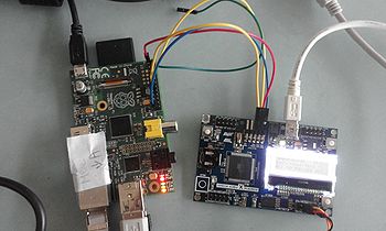
| + | <td> [[Fichier:PFE_P13_Branche_noeud.jpg |left|500 px]]</td> | ||
| + | <td>[[Fichier:Pfe_p13-p10.jpg|right|500 px]]</td> | ||
| + | </tr> | ||
| + | </table> | ||
| + | |||
| + | ===Information=== | ||
| + | <table border="2" align=center> | ||
| + | <tr> | ||
| + | <td width="600" align=center colspan="3" >Programmation </td> | ||
| + | </tr> | ||
| + | <tr> | ||
| + | <td width="100" align=center ></td> | ||
| + | <td width="100" align=center >PDI_DATA</td> | ||
| + | <td width="100" align=center >PDI_Clk</td> | ||
| + | </tr> | ||
| + | <tr> | ||
| + | <td width="100" align=center >Carte A</td> | ||
| + | <td width="100" align=center >GPIO 23</td> | ||
| + | <td width="100" align=center >GPIO 24</td> | ||
| + | </tr> | ||
| + | <tr> | ||
| + | <td width="100" align=center >Carte B</td> | ||
| + | <td width="100" align=center >GPIO 22</td> | ||
| + | <td width="100" align=center >GPIO 27</td> | ||
| + | </tr> | ||
| + | </table> | ||
| + | <br> | ||
| + | <table border="2" align=center> | ||
| + | <tr> | ||
| + | <td width="600" align=center colspan="3" >Vitesse de transfert </td> | ||
| + | </tr> | ||
| + | <tr> | ||
| + | <td width="100" align=center >USART</td> | ||
| + | <td width="100" align=center colspan="2">9 600 - 115 200</td> | ||
| + | </tr> | ||
| + | <tr> | ||
| + | <td width="100" align=center >USB</td> | ||
| + | <td width="100" align=center colspan="2"> -</td> | ||
| + | </tr> | ||
| + | </table> | ||
| + | <br> | ||
| + | <table border="2" align=center> | ||
| + | <tr> | ||
| + | <td width="600" align=center colspan="3" >Configuration </td> | ||
| + | </tr> | ||
| + | <tr> | ||
| + | <td width="100" align=center ></td> | ||
| + | <td width="100" align=center >Amont <br>(vers la raspberry)</td> | ||
| + | <td width="100" align=center >Aval <br> (vers les capteurs )</td> | ||
| + | </tr> | ||
| + | <tr> | ||
| + | <td width="100" align=center >Raspberry</td> | ||
| + | <td width="100" align=center >Réseau - Projet P10</td> | ||
| + | <td width="100" align=center >Carte A <br> Carte USB</td> | ||
| + | </tr> | ||
| + | <tr> | ||
| + | <td width="100" align=center >Carte A</td> | ||
| + | <td width="100" align=center >Raspberry</td> | ||
| + | <td width="100" align=center >Carte B</td> | ||
| + | </tr> | ||
| + | <tr> | ||
| + | <td width="100" align=center >Carte B</td> | ||
| + | <td width="100" align=center >-Carte A <br>- Carte USB</td> | ||
| + | <td width="100" align=center >NC</td> | ||
| + | </tr> | ||
| + | <tr> | ||
| + | <td width="100" align=center >Carte USB</td> | ||
| + | <td width="100" align=center >Raspberry</td> | ||
| + | <td width="100" align=center >Carte B</td> | ||
| + | </tr> | ||
| + | </table> | ||
| + | <br> | ||
| + | <table border="2" align=center> | ||
| + | <tr> | ||
| + | <td width="600" align=center colspan="3" >Connections </td> | ||
| + | </tr> | ||
| + | <tr> | ||
| + | <td width="300" align=center colspan="3" >Carte Xmega-A3BU </td> | ||
| + | </tr> | ||
| + | <tr> | ||
| + | <td width="100" align=center ></td> | ||
| + | <td width="100" align=center >Port J1</td> | ||
| + | <td width="100" align=center >Port J2</td> | ||
| + | </tr> | ||
| + | <tr> | ||
| + | <td width="100" align=center >Carte A</td> | ||
| + | <td width="100" align=center >Broche Rx et Tx <br>USART vers la Raspberry</td> | ||
| + | <td width="100" align=center >Broche Rx et Tx <br>USART vers la carte B</td> | ||
| + | </tr> | ||
| + | <tr> | ||
| + | <td width="100" align=center >Carte B</td> | ||
| + | <td width="100" align=center >Broche Rx et Tx <br>USART vers la carte A</td> | ||
| + | <td width="100" align=center >Broche Rx et Tx <br>USART vers la carte USB</td> | ||
| + | </tr> | ||
| + | <tr> | ||
| + | <td width="300" align=center colspan="3" >Raspberry </td> | ||
| + | </tr> | ||
| + | <tr> | ||
| + | <td width="100" align=center >Broche</td> | ||
| + | <td width="100" align=center colspan="2"></td> | ||
| + | </tr> | ||
| + | <tr> | ||
| + | <td width="100" align=center >1</td> | ||
| + | <td width="100" align=center colspan="2">Alimentation de la carte A</td> | ||
| + | </tr> | ||
| + | <tr> | ||
| + | <td width="100" align=center >8</td> | ||
| + | <td width="100" align=center colspan="2">USART TX</td> | ||
| + | </tr> | ||
| + | <tr> | ||
| + | <td width="100" align=center >10</td> | ||
| + | <td width="100" align=center colspan="2">USART RX</td> | ||
| + | </tr> | ||
| + | <tr> | ||
| + | <td width="100" align=center >13</td> | ||
| + | <td width="100" align=center colspan="2">PDI Clk carte B</td> | ||
| + | </tr> | ||
| + | <tr> | ||
| + | <td width="100" align=center >14</td> | ||
| + | <td width="100" align=center colspan="2">GND Carte A</td> | ||
| + | </tr> | ||
| + | <tr> | ||
| + | <td width="100" align=center >15</td> | ||
| + | <td width="100" align=center colspan="2">PDI Data Carte B</td> | ||
| + | </tr> | ||
| + | <tr> | ||
| + | <td width="100" align=center >16</td> | ||
| + | <td width="100" align=center colspan="2">PDI Data carte A</td> | ||
| + | </tr> | ||
| + | <tr> | ||
| + | <td width="100" align=center >17</td> | ||
| + | <td width="100" align=center colspan="2">Alimentation Carte B</td> | ||
| + | </tr> | ||
| + | <tr> | ||
| + | <td width="100" align=center >18</td> | ||
| + | <td width="100" align=center colspan="2">PDI Clock Carte A<tr> | ||
| + | </tr> | ||
| + | <tr> | ||
| + | <td width="100" align=center >25</td> | ||
| + | <td width="100" align=center colspan="2">GND Carte B</td> | ||
| + | </tr> | ||
| + | </table> | ||
| + | <br> | ||
| + | <table border="2" align=center> | ||
| + | <tr> | ||
| + | <td width="600" align=center colspan="3" >Câble de connexion </td> | ||
| + | </tr> | ||
| + | <tr> | ||
| + | <td width="100" align=center >Couleur</td> | ||
| + | <td width="100" align=center ></td> | ||
| + | </tr> | ||
| + | <tr> | ||
| + | <td width="100" align=center >Rouge</td> | ||
| + | <td width="100" align=center >+3.3 V</td> | ||
| + | </tr> | ||
| + | <tr> | ||
| + | <td width="100" align=center >Bleu</td> | ||
| + | <td width="100" align=center >GND</td> | ||
| + | </tr> | ||
| + | <tr> | ||
| + | <td width="100" align=center >Jaune</td> | ||
| + | <td width="100" align=center >PDI </td> | ||
| + | </tr> | ||
| + | <tr> | ||
| + | <td width="100" align=center >Vert /Jaune</td> | ||
| + | <td width="100" align=center >UART</td> | ||
| + | </tr> | ||
| + | </table> | ||
| + | |||
| + | ==Plateforme == | ||
| + | ===Nœud 1 === | ||
| + | ====Composition ==== | ||
| + | Le nœud 1 est constitué de :<br> | ||
| + | carte mère : <br> | ||
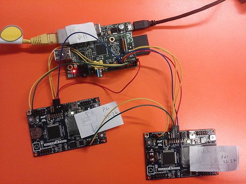
| + | -1 Raspberry PI2<br> | ||
| + | -2 cartes EVB-USB2517<br> | ||
| + | <br> | ||
| + | carte fille :<br> | ||
| + | -6 cartes d'essai Xplained <br><br> | ||
| + | carte petite fille :<br> | ||
| + | Ces cartes ne sont pas implantées sur le nœud. On simulera les capteurs.<br><br> | ||
| + | |||
| + | ====Implantation ==== | ||
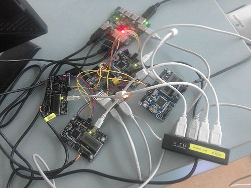
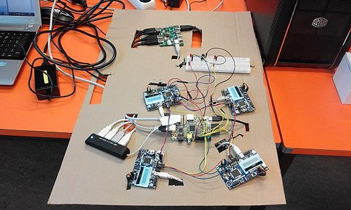
| + | [[Fichier:Pfe_p13_noeud_1.jpg |500 px|center]] | ||
| + | |||
| + | ====Information==== | ||
| + | <table border="2" align=center> | ||
| + | <tr> | ||
| + | <td width="250" align=center rowspan="2"></td> | ||
| + | <td width="100" align=center colspan="2">PDI_DATA</td> | ||
| + | <td width="100" align=center colspan="2">PDI_CLOCK</td> | ||
| + | </tr> | ||
| + | |||
| + | <tr> | ||
| + | <td width="100" align=center>Broche</td> | ||
| + | <td width="100" align=center>Gpio</td> | ||
| + | <td width="100" align=center>Broche</td> | ||
| + | <td width="100" align=center>Gpio</td> | ||
| + | </tr> | ||
| + | |||
| + | <tr> | ||
| + | <td width="100" align=center>Carte A</td> | ||
| + | <td width="100" align=center>11</td> | ||
| + | <td width="100" align=center>17</td> | ||
| + | <td width="100" align=center>13</td> | ||
| + | <td width="100" align=center>27</td> | ||
| + | </tr> | ||
| + | <tr> | ||
| + | <td width="100" align=center>Carte B</td> | ||
| + | <td width="100" align=center>12</td> | ||
| + | <td width="100" align=center>18</td> | ||
| + | <td width="100" align=center>22</td> | ||
| + | <td width="100" align=center>25</td> | ||
| + | </tr> | ||
| + | <tr> | ||
| + | <td width="100" align=center>Carte C</td> | ||
| + | <td width="100" align=center>33</td> | ||
| + | <td width="100" align=center>13</td> | ||
| + | <td width="100" align=center>35</td> | ||
| + | <td width="100" align=center>19</td> | ||
| + | </tr> | ||
| + | <tr> | ||
| + | <td width="100" align=center>Carte D </td> | ||
| + | <td width="100" align=center>16</td> | ||
| + | <td width="100" align=center>23</td> | ||
| + | <td width="100" align=center>18</td> | ||
| + | <td width="100" align=center>24</td> | ||
| + | </tr> | ||
| + | <tr> | ||
| + | <td width="100" align=center>Carte E </td> | ||
| + | <td width="100" align=center>36</td> | ||
| + | <td width="100" align=center>16</td> | ||
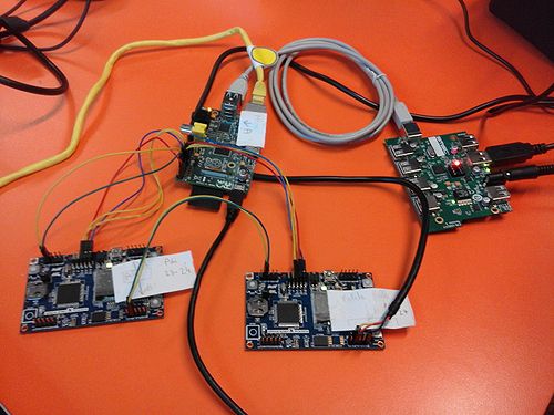
| + | <td width="100" align=center>38</td> | ||
| + | <td width="100" align=center>20</td> | ||
| + | </tr> | ||
| + | <tr> | ||
| + | <td width="100" align=center>Carte F </td> | ||
| + | <td width="100" align=center>15</td> | ||
| + | <td width="100" align=center>22</td> | ||
| + | <td width="100" align=center>37</td> | ||
| + | <td width="100" align=center>26</td> | ||
| + | </tr> | ||
| + | </table> | ||
| + | <br> | ||
| + | <table border="2" align=center> | ||
| + | <tr> | ||
| + | <td width="600" align=center colspan="3" >Interface UART </td> | ||
| + | </tr> | ||
| + | <tr> | ||
| + | <td width="100" align=center >Carte A</td> | ||
| + | <td width="100" align=center >ttyUSB0</td> | ||
| + | </tr> | ||
| + | <tr> | ||
| + | <td width="100" align=center >Carte B</td> | ||
| + | <td width="100" align=center >ttyUSB1</td> | ||
| + | </tr> | ||
| + | <tr> | ||
| + | <td width="100" align=center >Carte C</td> | ||
| + | <td width="100" align=center >ttyUSB2</td> | ||
| + | </tr> | ||
| + | <tr> | ||
| + | <td width="100" align=center >Carte D</td> | ||
| + | <td width="100" align=center >ttyUSB3</td> | ||
| + | </tr> | ||
| + | <tr> | ||
| + | <td width="100" align=center >Carte E</td> | ||
| + | <td width="100" align=center >ttyUSB4</td> | ||
| + | </tr> | ||
| + | <tr> | ||
| + | <td width="100" align=center >Carte F</td> | ||
| + | <td width="100" align=center >ttyUSB5</td> | ||
| + | </tr> | ||
| + | </table> | ||
| + | |||
| + | <br> | ||
| + | <table border="2" align=center> | ||
| + | <tr> | ||
| + | <td width="600" align=center colspan="3" >Vitesse de transfert </td> | ||
| + | </tr> | ||
| + | <tr> | ||
| + | <td width="100" align=center >USART</td> | ||
| + | <td width="100" align=center colspan="2"> 115 200 </td> | ||
| + | </tr> | ||
| + | <tr> | ||
| + | <td width="100" align=center >USB</td> | ||
| + | <td width="100" align=center colspan="2"> -</td> | ||
| + | </tr> | ||
| + | </table> | ||
| + | <br><br> | ||
| + | <table border="2" align=center> | ||
| + | <tr> | ||
| + | <td width="600" align=center colspan="3" >Câble de connexion </td> | ||
| + | </tr> | ||
| + | <tr> | ||
| + | <td width="100" align=center >Couleur</td> | ||
| + | <td width="100" align=center ></td> | ||
| + | </tr> | ||
| + | <tr> | ||
| + | <td width="100" align=center >Rouge</td> | ||
| + | <td width="100" align=center >+3.3 V</td> | ||
| + | </tr> | ||
| + | <tr> | ||
| + | <td width="100" align=center >Bleu</td> | ||
| + | <td width="100" align=center >GND</td> | ||
| + | </tr> | ||
| + | <tr> | ||
| + | <td width="100" align=center >Jaune</td> | ||
| + | <td width="100" align=center >PDI </td> | ||
| + | </tr> | ||
| + | </table> | ||
| + | <br><br> | ||
| + | |||
| + | ===Nœud 2 === | ||
| + | ====Composition ==== | ||
| + | Le nœud 2 est constitué de :<br> | ||
| + | carte mère : <br> | ||
| + | -1 Raspberry PI<br> | ||
| + | -1 carte EVB-USB2517<br> | ||
| + | -1 hub usb<br> | ||
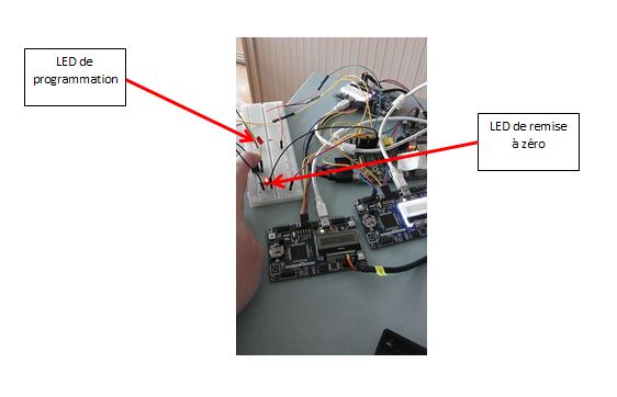
| + | -1 boutons poussoirs pour effectuer une remise à zéro<br> | ||
| + | -1 dispositif de visualisation <br> | ||
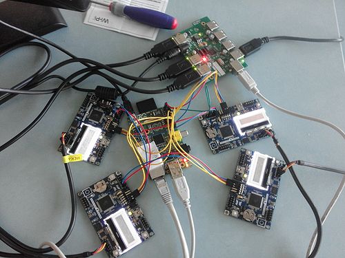
| + | [[Fichier:Pfe_p13_platine.JPG |center|500 px]] | ||
| + | <table border="1" align=center> | ||
| + | <tr align=center> | ||
| + | <td width="200px"></td> | ||
| + | <td width="200px">Etat</td> | ||
| + | <td width="200px">Action</td> | ||
| + | </tr> | ||
| + | <tr align=center> | ||
| + | <td rowspan="3">Led de programmation</td> | ||
| + | <td>Eteinte</td> | ||
| + | <td>Pas de remise à zéro en cours ni demandé </td> | ||
| + | </tr > | ||
| + | <tr align=center> | ||
| + | <td>Clignotante</td> | ||
| + | <td>/</td> | ||
| + | </tr > | ||
| + | <tr align=center> | ||
| + | <td>Allumé</td> | ||
| + | <td>Demande de remise à zéro et Remise à zéro en cours</td> | ||
| + | </tr > | ||
| + | <tr align=center> | ||
| + | <td rowspan="3">Led de remise à zéro</td> | ||
| + | <td>Eteinte</td> | ||
| + | <td>Pas de programmation en cours </td> | ||
| + | </tr > | ||
| + | <tr align=center> | ||
| + | <td>Clignotante</td> | ||
| + | <td>Programmation en cours</td> | ||
| + | </tr > | ||
| + | <tr align=center> | ||
| + | <td>Allumé</td> | ||
| + | <td>Erreur de programmation</td> | ||
| + | </tr > | ||
| + | </table> | ||
| + | <br> | ||
| + | carte fille :<br> | ||
| + | -4 cartes d'essai Xplained <br><br> | ||
| + | carte petite fille :<br> | ||
| + | Ces cartes ne sont pas implantées sur le nœud. On simulera les capteurs.<br><br> | ||
| + | |||
| + | ====Implantation ==== | ||
| + | |||
| + | <table align=center> | ||
| + | <tr align=center> | ||
| + | <td>Sans liaison USB</td> | ||
| + | <td>Avec liaison USB</td> | ||
| + | </tr> | ||
| + | <tr> | ||
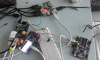
| + | <td> [[Fichier:Pfe_p13_noeud_2.jpg |500 px|center]]</td> | ||
| + | <td>[[Fichier:Pfe_p13_usb.jpg|center|500 px]]</td> | ||
| + | </tr> | ||
| + | </table> | ||
| + | |||
| + | ====Information==== | ||
| + | <table border="2" align=center> | ||
| + | <tr> | ||
| + | <td width="250" align=center colspan="5">Programmation</td> | ||
| + | </tr> | ||
| + | <tr> | ||
| + | <td width="250" align=center rowspan="2"></td> | ||
| + | <td width="100" align=center colspan="2">PDI_DATA</td> | ||
| + | <td width="100" align=center colspan="2">PDI_CLOCK</td> | ||
| + | </tr> | ||
| + | |||
| + | <tr> | ||
| + | <td width="100" align=center>Broche</td> | ||
| + | <td width="100" align=center>Gpio</td> | ||
| + | <td width="100" align=center>Broche</td> | ||
| + | <td width="100" align=center>Gpio</td> | ||
| + | </tr> | ||
| + | <tr> | ||
| + | <td width="100" align=center>Carte A </td> | ||
| + | <td width="100" align=center>16</td> | ||
| + | <td width="100" align=center>23</td> | ||
| + | <td width="100" align=center>18</td> | ||
| + | <td width="100" align=center>24</td> | ||
| + | </tr> | ||
| + | <tr> | ||
| + | <td width="100" align=center>Carte B</td> | ||
| + | <td width="100" align=center>15</td> | ||
| + | <td width="100" align=center>22</td> | ||
| + | <td width="100" align=center>13</td> | ||
| + | <td width="100" align=center>27</td> | ||
| + | </tr> | ||
| + | <tr> | ||
| + | <td width="100" align=center>Carte C</td> | ||
| + | <td width="100" align=center>19</td> | ||
| + | <td width="100" align=center>10</td> | ||
| + | <td width="100" align=center>21</td> | ||
| + | <td width="100" align=center>9</td> | ||
| + | </tr> | ||
| + | <tr> | ||
| + | <td width="100" align=center>Carte D </td> | ||
| + | <td width="100" align=center>11</td> | ||
| + | <td width="100" align=center>17</td> | ||
| + | <td width="100" align=center>12</td> | ||
| + | <td width="100" align=center>18</td> | ||
| + | </tr> | ||
| + | <tr> | ||
| + | </table> | ||
| + | <br> | ||
| + | <table border="2" align=center> | ||
| + | <tr> | ||
| + | <td width="600" align=center colspan="3" >Interface UART </td> | ||
| + | </tr> | ||
| + | <tr> | ||
| + | <td width="100" align=center >Carte A</td> | ||
| + | <td width="100" align=center >ttyUSB0</td> | ||
| + | </tr> | ||
| + | <tr> | ||
| + | <td width="100" align=center >Carte B</td> | ||
| + | <td width="100" align=center >ttyUSB1</td> | ||
| + | </tr> | ||
| + | <tr> | ||
| + | <td width="100" align=center >Carte C</td> | ||
| + | <td width="100" align=center >ttyUSB2</td> | ||
| + | </tr> | ||
| + | <tr> | ||
| + | <td width="100" align=center >Carte D</td> | ||
| + | <td width="100" align=center >ttyUSB3</td> | ||
| + | </tr> | ||
| + | </table> | ||
| + | <br> | ||
| + | <table border="2" align=center> | ||
| + | <tr> | ||
| + | <td width="600" align=center colspan="3" >Interface USB </td> | ||
| + | </tr> | ||
| + | <tr> | ||
| + | <td width="100" align=center >Carte A</td> | ||
| + | <td width="100" align=center >ttyACM0</td> | ||
| + | </tr> | ||
| + | <tr> | ||
| + | <td width="100" align=center >Carte B</td> | ||
| + | <td width="100" align=center >ttyACM1</td> | ||
| + | </tr> | ||
| + | <tr> | ||
| + | <td width="100" align=center >Carte C</td> | ||
| + | <td width="100" align=center >ttyACM2</td> | ||
| + | </tr> | ||
| + | <tr> | ||
| + | <td width="100" align=center >Carte D</td> | ||
| + | <td width="100" align=center >ttyACM3</td> | ||
| + | </tr> | ||
| + | </table> | ||
| + | <br> | ||
| + | <table border="2" align=center> | ||
| + | <tr> | ||
| + | <td width="600" align=center colspan="3" >Vitesse de transfert </td> | ||
| + | </tr> | ||
| + | <tr> | ||
| + | <td width="100" align=center >USART</td> | ||
| + | <td width="100" align=center colspan="2"> 115 200 baud </td> | ||
| + | </tr> | ||
| + | <tr> | ||
| + | <td width="100" align=center >USB</td> | ||
| + | <td width="100" align=center colspan="2"> 3.5 Mbits</td> | ||
| + | </tr> | ||
| + | </table> | ||
| + | <br><br> | ||
| + | <table border="2" align=center> | ||
| + | <tr> | ||
| + | <td width="600" align=center colspan="3" >Câble de connexion </td> | ||
| + | </tr> | ||
| + | <tr> | ||
| + | <td width="100" align=center >Couleur</td> | ||
| + | <td width="100" align=center ></td> | ||
| + | </tr> | ||
| + | <tr> | ||
| + | <td width="100" align=center >Rouge</td> | ||
| + | <td width="100" align=center >+3.3 V</td> | ||
| + | </tr> | ||
| + | <tr> | ||
| + | <td width="100" align=center >Bleu</td> | ||
| + | <td width="100" align=center >GND</td> | ||
| + | </tr> | ||
| + | <tr> | ||
| + | <td width="100" align=center >Jaune</td> | ||
| + | <td width="100" align=center >PDI </td> | ||
| + | </tr> | ||
| + | </table> | ||
| + | <br><br> | ||
| + | ===Code source === | ||
| + | '''<center>Les codes suivants sont implémenté sur la carte mère (Raspberry)</center>'''<br><br> | ||
| + | <table border="1" align="center"> | ||
| + | <tr align="center"> | ||
| + | <td>Procédure</td> | ||
| + | <td>Fichier</td> | ||
| + | <td>Nom de l'exécutable</td> | ||
| + | <td>Action réalisé par le programme</td> | ||
| + | <td>Note</td> | ||
| + | </tr> | ||
| + | |||
| + | <tr align="center"> | ||
| + | <td>Initialisation de la Raspberry</td> | ||
| + | <td>[[Média:Init.zip]]</td> | ||
| + | <td>./dem_noeud ou dem_noeud*</td> | ||
| + | <td>Initialisation des GPIO<br>Exécution du programme de la gestion du boutons poussoir en tache de fond</td> | ||
| + | <td>Ce code est à utilisé a chaque démarrage de la Raspberry</td> | ||
| + | </tr> | ||
| + | |||
| + | <tr align="center"> | ||
| + | <td>Remise a zéro</td> | ||
| + | <td>[[Média:Remise_à_zéro.zip]]</td> | ||
| + | <td>./raz ou raz*</td> | ||
| + | <td>Mettre les broches du PDI Clock à l'état bas</td> | ||
| + | <td>Ce programme est appellé par un appuie sur le bouton poussoir</td> | ||
| + | </tr> | ||
| + | |||
| + | <tr align="center"> | ||
| + | <td>Gestion du bouton poussoir</td> | ||
| + | <td>[[Média:Gestion_du_boutons_poussoir.zip]]</td> | ||
| + | <td>./bp ou bp*</td> | ||
| + | <td>Ce programme est lancé en tache de fond <br>Il est lancé au démarrage du noeud <br> Lorsque l'on appuie sur le boutons on appelle le programme RAZ qui remetra l'ensemble du noeud à zéro </td> | ||
| + | <td>Ce programme est appellé par le programme du boutons poussoirs</td> | ||
| + | </tr> | ||
| + | |||
| + | <tr align="center"> | ||
| + | <td>Programmation du noeud</td> | ||
| + | <td>[[Média:Programmation.zip]]</td> | ||
| + | <td>./programmer ou programmer*</td> | ||
| + | <td>Reprogrammation du noeud suivant le nombre d'argument </td> | ||
| + | <td></td> | ||
| + | </tr> | ||
| + | |||
| + | </table> | ||
| + | *ces commandes sont possible si on crée un path | ||
| + | '''<center>Les codes suivants sont implémenté sur la carte fille</center>'''<br><br> | ||
| + | Code d'exemple pour l'UART:[[Média:UART.zip]]<br> | ||
| + | Code d'exemple pour l'USB :[[Média:USB.zip]] <br><br> | ||
| + | |||
| + | Vous trouvez l'ensemble des codes dans ce fichier :[[Média:Lilliad_plateforme_code_source.zip]]<br><br> | ||
| + | |||
| + | ===Réalisation d'un support de présentation === | ||
| + | |||
| + | [[Fichier:Pfe_P13.jpg |center|500 px]] | ||
| + | |||
| + | ==Procédure et historique== | ||
| + | <br>'''<center>L’ensemble des procédures est automatisable. Le code servant à reprogrammer les cartes devra être adapter aux besoins du nœud</center>'''<br><br> | ||
| + | ===Mode de programmation=== | ||
| + | ====Programmation simple ==== | ||
| + | Ce câblage est le plus utilisé sur le nœud car on reprogramme une carte avec un fichier.<br> | ||
| + | Schéma :<br> | ||
| + | [[Fichier:Pfe_p13_10.jpg |350 px|center]]<br><br> | ||
| + | |||
| + | ====Programmation Multiple ==== | ||
| + | Ce cablage nous permet de connecter plusieurs carte ensemble afin d'utiliser qu'un seul programme<br> | ||
| + | Le schéma ci-dessous nous montre ce câblage :<br><br>[[Fichier:Pfe_p13_11.jpg |350 px|center]] | ||
| + | |||
| + | ===Procédure pour programmer un nœud === | ||
| + | La commande pour programmer un nœud est la suivante : programmer <br> | ||
| + | La commande a besoin d'argument pour reprogrammé le noeud. Ces arguments sont des fichier .hex<br> | ||
| + | En fonction du nombre d'argument le programme va réalisé les programmations suivantes :<br><br><br> | ||
| + | <table border="1" align=center> | ||
| + | <tr align=center> | ||
| + | <td>Nombre d'argument</td> | ||
| + | <td>Action</td> | ||
| + | </tr> | ||
| + | |||
| + | <tr align=center> | ||
| + | <td>1</td> | ||
| + | <td>Reprogrammation de l’ensemble du nœud <br>Reprogrammation d’une carte</td> | ||
| + | </tr> | ||
| + | |||
| + | <tr align=center> | ||
| + | <td>2</td> | ||
| + | <td>Reprogrammation de la carte A<br>Reprogrammation de la carte B</td> | ||
| + | </tr> | ||
| + | |||
| + | <tr align=center> | ||
| + | <td>3</td> | ||
| + | <td>Reprogrammation de la carte A<br>Reprogrammation de la carte B<br>Reprogrammation de la carte C</td> | ||
| + | </tr> | ||
| + | |||
| + | <tr align=center> | ||
| + | <td>4</td> | ||
| + | <td>Reprogrammation de la carte A<br>Reprogrammation de la carte B<br>Reprogrammation de la carte C<br>Reprogrammation de la carte D</td> | ||
| + | </tr> | ||
| + | |||
| + | <tr align=center> | ||
| + | <td>5</td> | ||
| + | <td>Reprogrammation de la carte A<br>Reprogrammation de la carte B<br>Reprogrammation de la carte C<br>Reprogrammation de la carte D<br>Reprogrammation de la carte E</td> | ||
| + | </tr> | ||
| + | |||
| + | <tr align=center> | ||
| + | <td>6</td> | ||
| + | <td>Reprogrammation de la carte A<br>Reprogrammation de la carte B<br>Reprogrammation de la carte C<br>Reprogrammation de la carte D<br>Reprogrammation de la carte E<br>Reprogrammation de la carte F</td> | ||
| + | </tr> | ||
| + | |||
| + | <tr align=center> | ||
| + | <td>7</td> | ||
| + | <td>Reprogrammation de la carte A<br>Reprogrammation de la carte B<br>Reprogrammation de la carte C<br>Reprogrammation de la carte D<br>Reprogrammation de la carte E<br>Reprogrammation de la carte F<br>Reprogrammation de la carte G</td> | ||
| + | </tr> | ||
| + | |||
| + | <tr align=center> | ||
| + | <td>8</td> | ||
| + | <td>Reprogrammation de la carte A<br>Reprogrammation de la carte B<br>Reprogrammation de la carte C<br>Reprogrammation de la carte D<br>Reprogrammation de la carte E<br>Reprogrammation de la carte F<br>Reprogrammation de la carte G<br>Reprogrammation de la carte H</td> | ||
| + | </tr> | ||
| + | |||
| + | <tr align=center> | ||
| + | <td>9 et + </td> | ||
| + | <td>Reprogrammation de la carte A<br>Reprogrammation de la carte B<br>Reprogrammation de la carte C<br>Reprogrammation de la carte D<br>Reprogrammation de la carte E<br>Reprogrammation de la carte F<br>Reprogrammation de la carte G<br>Reprogrammation de la carte H<br>Reprogrammation de la carte I</td> | ||
| + | </tr> | ||
| + | |||
| + | </table> | ||
| + | Capture d'écran du programme:<br> | ||
| + | [[Fichier:Procedure_program.JPG |center]] | ||
| + | |||
| + | ===Procédure pour remettre à zéro un nœud === | ||
| + | Pour remettre à zéro l'ensemble du nœud il faut appuyer sur le boutons poussoirs pendant 5 secondes. Ensuite la raspberry remettra le nœud à zéro via le programme RAZ. | ||
| + | Capture d'écran de la remise à zéro. | ||
| + | [[Fichier:Raz.JPG |center]]<br> | ||
| + | A cela s'ajoute une LED qui s'allume dés que la demande du boutons a été prise en compte et ceux jusqu’à la fin de la procédure de la remise à zéro. | ||
| + | <table border="0" align=center> | ||
| + | <tr> | ||
| + | <td>[[Fichier:Pfe_p13_raz_2.jpg |200 px]] | ||
| + | </td> | ||
| + | <td>[[Fichier:Pfe_p13_raz_1.jpg |500 px]] | ||
| + | </td> | ||
| + | </tr> | ||
| + | </table> | ||
| + | |||
| + | ===Procédure de démarrage=== | ||
| + | Cette procédure doit être exécuter à chaque démarrage de la Raspberry. Cette procédure initialise les GPIO, remet à zéro le nœud et lance en tache de fond la gestion du boutons poussoirs | ||
| + | Capture d'écran de la procédure de démarrage:<br> | ||
| + | [[Fichier:Procedure_dem_noeud.JPG|500 px |center]] | ||
| + | |||
| + | ===Historique des bug sur la plateforme === | ||
| + | -25 janvier<br> | ||
| + | Programmation (PDI ) : Error : failed to rewrite at the adress 4096 -> Reprogrammation effectué<br> | ||
| + | 8 tentative avant la reprogrammation de la flash <br><br> | ||
| + | - 3 février <br> | ||
| + | Programmation (PDI ) : Error : failed to rewrite at the adress 0 sur les GPIO 5 et 6 -> changement du mapping de la raspberry<br><br> | ||
| + | - 3 février au 9 février<br> | ||
| + | aucun problème n'a été constaté . Des tests sont effectués régulièrement sur la reprogrammation des cartes et sur la lecture des données<br><br> | ||
| + | - 9 février 16:00 <br> | ||
| + | Le nœud 1 est inaccessible en attente de la modifications du réseau par le projet P10 <br><br> | ||
| + | - 9 février 16:00 - 16 février 16:00 <br> | ||
| + | Problème de configuration réseaux. Les cartes sont ré-configurés en local. En dehors des heures de projet les nœuds sont hors tension <br><br> | ||
| + | - 10 février <br> | ||
| + | Aucun test de remonter de donné n a pu être réalisé .Des tests en local ont effectué après une journée de non alimentation des nœuds. Il s'est relevé l'erreur suivante :Error Fail to rewrite at the adres xxxx.<br>Recherche du problème<br><br> | ||
| + | - 11 février<br> | ||
| + | Des tests en local sont en cours afin de trouver une procédure de redémarrage.Les premiers semble aboutir. Le noeud a été mis au repose pendant une journée afin de recommencer la procédure<br><br> | ||
| + | - 12 février<br> | ||
| + | Suite des tests de la procédure de redémarrage<br> | ||
| + | - Programmation (PDI ) : Error : failed to rewrite at the adress 8704 -> Reprogrammation effectué <br> | ||
| + | - RAZ : Error :failed to perform chip erase ->Opération effectué<br> | ||
| + | Taux de réussite des tests : 7/10<br> | ||
| + | La procédure de démarrage est quasi opérationnel . Les prochains tests nous permettrons de fiabiliser la procédure<br><br> | ||
| + | - 15 février<br> | ||
| + | Procédure de redémarrage fiabiliser. Nous sommes en mesure de reprogrammer l'ensemble du nœud avec zéro erreur<br> | ||
| + | '''Nouvelle procédure de programmation mise en place. Les résultats est de 100 % de réussite a chaque programmation , chaque redémarrage quelque soit le programme<br>'''<br> | ||
| + | - 16 février<br> | ||
| + | Déploiement de la nouvelle méthode de programmation sur les deux noeuds. Le nœud 2 est opérationnel pour effectuer une démonstration lors de la soutenance. Le réseaux a été rétabli à 16h<br><br> | ||
| + | - 17 février<br> | ||
| + | Cette journée a été consacrée à la prise en main de la plateforme existante par les encadrants.Aucun problème constaté sur la plateforme<br><br> | ||
| + | - 18 février<br> | ||
| + | Ajout de la fonction Remise à zéro du nœud par simple appui sur le boutons poussoirs et de la procédure de démarrage. Arrêt temporaire de développement de la plateforme<br><br> | ||
| + | - 19 février - 23 février<br> | ||
| + | Rédactions des livrables de fin de projet <br><br> | ||
| + | - 22 février<br> | ||
| + | Tournage de la vidéo<br><br> | ||
| + | - 25 février<br> | ||
| + | Rendu des codes sources. Fin du projet<br><br> | ||
| + | |||
| + | ==Évolution vers un nœud implantable dans un lieux public == | ||
| + | ===Mesure de l' énergie=== | ||
| + | Implantée sur la carte mère la mesure de l'énergie nous indiquera la consommation du nœud. Cette dernière sera mesurer à l'aide de convertisseurs analogique-numérique<br> | ||
| + | La consomation ne peut pas être mesuré directement. Pour cela on va utiliser une résistance de quelque ohms.La façon la plus simple est de connaitre les éléments suivants :<br> | ||
| + | -la valeur de la résistance<br> | ||
| + | -la tension <br><br> | ||
| + | Formule à utiliser pour estimer la puissance:<br> | ||
| + | On pose :<br> | ||
| + | Mr : valeur issue du CAN<br> | ||
| + | Ir: Estimation du courant dans la résistance<br> | ||
| + | U : tension d'alimentation<br><br> | ||
| + | Afin d'estimer le courant de la résistance il faut convertir Mr suivant la courbe du CAN. Cette dernière est linéaire.<br> | ||
| + | Un fois la valeur convertie on aura à appliquer la formule suivante : P=U*Ir<br> | ||
| + | |||
| + | ===Modification de la trame de donnée=== | ||
| + | La trame utilisé lors des différents essai ne correspond pas totalement aux besoins de l'utilisateur. C'est pour cette raison que nous allons remplacé la trame par celle-ci:<br><br> | ||
| + | <table border="2" align=center> | ||
| + | <tr align=center> | ||
| + | <td colspan="8" >En tête</td> | ||
| + | </tr> | ||
| + | <tr> | ||
| + | <td width="100" align=center>Mode<br>(Full ou simple)</td> | ||
| + | <td width="250" align=center>Mode de transmission<br> ( S : USART ; U : USB ; R : Radio)</td> | ||
| + | <td width="100" align=center>ID</td> | ||
| + | </tr> | ||
| + | <tr align=center> | ||
| + | <td colspan="8" >Corps</td> | ||
| + | </tr> | ||
| + | <tr align=center> | ||
| + | <td width="100" align=center>Numéro de la carte fille</td> | ||
| + | <td width="250" align=center>Data de la carte <br>petite fille 1 </td> | ||
| + | <td width="100" align=center>Data de la carte <br>petite fille 2 </td> | ||
| + | </tr> | ||
| + | </table> | ||
| + | <br> | ||
| + | |||
| + | ===Alimentation externe du nœud === | ||
| + | Actuellement nous alimentons le nœud via la raspberry. L’idée est de passé sur une alimentation secteur 230 V. | ||
| + | [[Fichier:Pfe_p13_alimentation_externe.JPG |center ]] | ||
| + | <br><br> | ||
| + | ===Remplacement des cartes d'essais === | ||
| + | '''Carte mère'''<br> | ||
| + | On conserve la Raspberry ainsi que l’hub USB. On supprimera les câbles série USB par une carte dédiée à l’UART.<br> | ||
| + | Cette carte sera composée d’un ATxmega32A4U qui a les caractéristiques suivantes :<br> | ||
| + | - Reprogrammation en PDI<br> | ||
| + | - 5 ports USART<br> | ||
| + | - CAN<br> | ||
| + | - USB<br> | ||
| + | - 7 port SPI<br> | ||
| + | - 2 portI2C<br><br> | ||
| + | Pour plus d'informations cliquez [http://www.atmel.com/devices/ATXMEGA32A4U.aspx?tab=parameters ici]<br> | ||
| + | Pour les bessoins du noeud nous avons décider de mettre 2 ATxmega32A4U . Ce choix nous permet d'avoir un demi noeud toujours opérationnel. De plus nous avons la possibilité de reprogrammer les deux cartes avec le même fichier .<br> | ||
| + | Exemple de configuration des ports<br> | ||
| + | <table border="1" align=center> | ||
| + | <tr align=center> | ||
| + | <td width="100">Fonction</td> | ||
| + | <td width="100">Port </td> | ||
| + | <td width="100"> Numéro Pin </td> | ||
| + | <td width="100"> Pin Fonctions </td> | ||
| + | <td width="100"> Numéro Pin </td> | ||
| + | <td width="100"> Pin Fonctions </td> | ||
| + | <td width="200">Carte</td> | ||
| + | </tr> | ||
| + | <tr align=center> | ||
| + | <td colspan="7" align=center height="50">Reprogrammation </td> | ||
| + | </tr> | ||
| + | <tr align=center> | ||
| + | <td>PDI</td> | ||
| + | <td>R</td> | ||
| + | <td>35</td> | ||
| + | <td>Clock</td> | ||
| + | <td>34</td> | ||
| + | <td>Data</td> | ||
| + | <td>-</td> | ||
| + | </tr> | ||
| + | <tr align=center> | ||
| + | <td colspan="7" align=center height="50">Carte Microcontrôleur numéro 1</td> | ||
| + | </tr> | ||
| + | <tr align=center> | ||
| + | <td>USART 1</td> | ||
| + | <td>C</td> | ||
| + | <td>12</td> | ||
| + | <td>Rx</td> | ||
| + | <td>13</td> | ||
| + | <td>Tx</td> | ||
| + | <td>Liaison vers la Raspberry</td> | ||
| + | </tr> | ||
| + | |||
| + | <tr align=center> | ||
| + | <td>USART 2</td> | ||
| + | <td>C</td> | ||
| + | <td>16</td> | ||
| + | <td>Rx</td> | ||
| + | <td>17</td> | ||
| + | <td>Tx</td> | ||
| + | <td>Carte B</td> | ||
| + | </tr> | ||
| + | |||
| + | <tr align=center> | ||
| + | <td>USART 3</td> | ||
| + | <td>D</td> | ||
| + | <td>22</td> | ||
| + | <td>Rx</td> | ||
| + | <td>23</td> | ||
| + | <td>Tx</td> | ||
| + | <td>Carte C</td> | ||
| + | </tr> | ||
| + | |||
| + | <tr align=center> | ||
| + | <td>USART 4</td> | ||
| + | <td>D</td> | ||
| + | <td>26</td> | ||
| + | <td>Rx</td> | ||
| + | <td>27</td> | ||
| + | <td>Tx</td> | ||
| + | <td>Carte D</td> | ||
| + | </tr> | ||
| + | |||
| + | <tr align=center> | ||
| + | <td>USART 5</td> | ||
| + | <td>E</td> | ||
| + | <td>32</td> | ||
| + | <td>Rx</td> | ||
| + | <td>33</td> | ||
| + | <td>Tx</td> | ||
| + | <td>Carte E</td> | ||
| + | </tr> | ||
| + | <tr align=center> | ||
| + | <td colspan="7" align=center height="50">Carte Microcontrôleur numéro 2</td> | ||
| + | </tr> | ||
| + | <tr align=center> | ||
| + | <td>USART 1</td> | ||
| + | <td>C</td> | ||
| + | <td>12</td> | ||
| + | <td>Rx</td> | ||
| + | <td>13</td> | ||
| + | <td>Tx</td> | ||
| + | <td>Liaison vers la Raspberry</td> | ||
| + | </tr> | ||
| + | <tr align=center> | ||
| + | <td>USART 2</td> | ||
| + | <td>C</td> | ||
| + | <td>16</td> | ||
| + | <td>Rx</td> | ||
| + | <td>17</td> | ||
| + | <td>Tx</td> | ||
| + | <td>Carte F</td> | ||
| + | </tr> | ||
| + | |||
| + | <tr align=center> | ||
| + | <td>USART 3</td> | ||
| + | <td>D</td> | ||
| + | <td>22</td> | ||
| + | <td>Rx</td> | ||
| + | <td>23</td> | ||
| + | <td>Tx</td> | ||
| + | <td>Carte G</td> | ||
| + | </tr> | ||
| + | |||
| + | <tr align=center> | ||
| + | <td>USART 4</td> | ||
| + | <td>D</td> | ||
| + | <td>26</td> | ||
| + | <td>Rx</td> | ||
| + | <td>27</td> | ||
| + | <td>Tx</td> | ||
| + | <td>Carte H</td> | ||
| + | </tr> | ||
| + | |||
| + | <tr align=center> | ||
| + | <td>USART 5</td> | ||
| + | <td>E</td> | ||
| + | <td>32</td> | ||
| + | <td>Rx</td> | ||
| + | <td>33</td> | ||
| + | <td>Tx</td> | ||
| + | <td>Carte I</td> | ||
| + | </tr> | ||
| + | </table> | ||
| + | |||
| + | Schéma de la carte mère :<br> | ||
| + | [[Fichier:Pfe_p13_carte_mere_final.JPG|500 px|center]]<br> | ||
| + | Le (1) nous montre le remplacements des cartes.Cette carte pourra mesuré de l’énergie d'un demi nœud<br><br> | ||
| + | '''Carte fille'''<br> | ||
| + | La carte Xplained sera remplacée par un ATxmega256C3 qui a les caractéristiques suivantes :<br> | ||
| + | - Reprogrammation en PDI<br> | ||
| + | - 3 ports USART<br> | ||
| + | - CAN<br> | ||
| + | - USB<br> | ||
| + | - 5 port SPI<br> | ||
| + | - 2 portI2C<br><br> | ||
| + | Pour plus d'informations cliquez [http://www.atmel.com/devices/atxmega256c3.aspx?tab=parameters ici]<br> | ||
| + | Exemple de configuration des ports<br> | ||
| + | <table border="1" align=center> | ||
| + | <tr align=center> | ||
| + | <td width="100">Fonction</td> | ||
| + | <td width="100">Port </td> | ||
| + | <td width="100"> Numéro Pin </td> | ||
| + | <td width="100"> Pin Fonctions </td> | ||
| + | <td width="100"> Numéro Pin </td> | ||
| + | <td width="100"> Pin Fonctions </td> | ||
| + | <td width="100"> Numéro Pin </td> | ||
| + | <td width="100"> Pin Fonctions </td> | ||
| + | <td width="100"> Numéro Pin </td> | ||
| + | <td width="100"> Pin Fonctions </td> | ||
| + | </tr> | ||
| + | <tr align=center> | ||
| + | <td colspan="10" align=center height="50">Reprogrammation </td> | ||
| + | </tr> | ||
| + | <tr align=center> | ||
| + | <td>PDI</td> | ||
| + | <td>R</td> | ||
| + | <td>57</td> | ||
| + | <td>Clock</td> | ||
| + | <td>56</td> | ||
| + | <td>Data</td> | ||
| + | <td colspan="4">/</td> | ||
| + | </tr> | ||
| + | <tr align=center> | ||
| + | <td colspan="10" align=center height="50">Connexion pour la carte petite fille 1</td> | ||
| + | </tr> | ||
| + | <tr align=center> | ||
| + | <td>USART </td> | ||
| + | <td>C</td> | ||
| + | <td>18</td> | ||
| + | <td>Rx</td> | ||
| + | <td>19</td> | ||
| + | <td>Tx</td> | ||
| + | <td colspan="4">/</td> | ||
| + | </tr> | ||
| + | <tr align=center> | ||
| + | <td>I2C </td> | ||
| + | <td>C</td> | ||
| + | <td>16</td> | ||
| + | <td>SDA</td> | ||
| + | <td>17</td> | ||
| + | <td>SCL</td> | ||
| + | <td colspan="4">/</td> | ||
| + | </tr> | ||
| + | <tr align=center> | ||
| + | <td>SPI </td> | ||
| + | <td>C</td> | ||
| + | <td>20</td> | ||
| + | <td>/(SS)</td> | ||
| + | <td>21</td> | ||
| + | <td>MOSI</td> | ||
| + | <td>22</td> | ||
| + | <td>MISO</td> | ||
| + | <td>23</td> | ||
| + | <td>SCK</td> | ||
| + | </tr> | ||
| + | |||
| + | <tr align=center> | ||
| + | <td colspan="10" align=center height="50">Connexion pour la carte petite fille 2</td> | ||
| + | </tr> | ||
| + | <tr align=center> | ||
| + | <td>USART </td> | ||
| + | <td>E</td> | ||
| + | <td>38</td> | ||
| + | <td>Rx</td> | ||
| + | <td>39</td> | ||
| + | <td>Tx</td> | ||
| + | <td colspan="4">/</td> | ||
| + | </tr> | ||
| + | <tr align=center> | ||
| + | <td>I2C </td> | ||
| + | <td>E</td> | ||
| + | <td>36</td> | ||
| + | <td>SDA</td> | ||
| + | <td>37</td> | ||
| + | <td>SCL</td> | ||
| + | <td colspan="4">/</td> | ||
| + | </tr> | ||
| + | <tr align=center> | ||
| + | <td>SPI </td> | ||
| + | <td>D</td> | ||
| + | <td>30</td> | ||
| + | <td>/(SS)</td> | ||
| + | <td>31</td> | ||
| + | <td>MOSI</td> | ||
| + | <td>32</td> | ||
| + | <td>MISO</td> | ||
| + | <td>33</td> | ||
| + | <td>SCK</td> | ||
| + | </tr> | ||
| + | </table> | ||
| + | '''Carte petite fille'''<br> | ||
| + | Actuellement nous fonctionnons avec un générateur de trame il sera remplacé par une carte STM32F4<br> | ||
| + | [[Fichier:PFE_P13_carte STM32F4.jpg |300 px|center]] | ||
| + | |||
| + | <br><br> | ||
| + | Les différents changements nous conduirons a ce schéma : <br> | ||
| + | [[Fichier:Pfe_noeud_terminal.JPG|center]]<br> | ||
| + | Légende :<br> | ||
| + | <table border="1" align=center> | ||
| + | <tr align=center> | ||
| + | <td width="150">Couleur</td> | ||
| + | <td width="150">Fonction associés</td> | ||
| + | </tr> | ||
| + | <tr align=center> | ||
| + | <td>Violet</td> | ||
| + | <td>I2C</td> | ||
| + | </tr> | ||
| − | = | + | <tr align=center> |
| − | + | <td>Bordeaux</td> | |
| + | <td>SPI</td> | ||
| + | </tr> | ||
| − | + | <tr align=center> | |
| − | + | <td>Orange</td> | |
| − | + | <td>UART</td> | |
| − | + | </tr> | |
| − | = | + | <tr align=center> |
| − | + | <td>Noir</td> | |
| − | + | <td>Alimentation</td> | |
| + | </tr> | ||
| − | + | <tr align=center> | |
| − | + | <td>Vert</td> | |
| + | <td>PDI</td> | ||
| + | </tr> | ||
| − | = | + | <tr align=center> |
| − | + | <td>Bleu</td> | |
| − | + | <td>USB</td> | |
| − | + | </tr> | |
| − | |||
| − | |||
| − | |||
| − | |||
| − | |||
| − | |||
| − | |||
| − | |||
| − | |||
| − | |||
| − | |||
| − | |||
| − | |||
| − | |||
| − | |||
| − | |||
| − | |||
| − | |||
| − | |||
| − | |||
| − | |||
| − | |||
| − | |||
| − | |||
| − | |||
| − | |||
| − | |||
| − | |||
| − | |||
| − | |||
| − | |||
| − | |||
| − | |||
| − | |||
| − | |||
| − | |||
| − | |||
| − | |||
| − | |||
| − | |||
| − | |||
| − | |||
| − | |||
| − | |||
| − | |||
| − | |||
| − | |||
| − | |||
| − | |||
| − | |||
| − | = | + | <tr align=center> |
| − | + | <td>Rouge</td> | |
| − | + | <td>PDI + USB + UART</td> | |
| − | + | </tr> | |
| − | + | </table> | |
| − | + | <br><br> | |
| − | + | '''La sélection des microcontrôleurs est donnée à titre d'exemple. Vous avez la possibilité de choisir vôtre microcontrôleur en utilisant l’outil de sélection de chez Atmel qui se trouve [http://www.atmel.com/v2pfresults.aspx#%28actives:!%28%29,data:%28area:%27%27,category:%2734864%27,pm:!%28%29,view:list%29,sc:1%29 ici ]''' | |
| − | |||
| − | == | + | ==Avancement du projet== |
| − | + | Dans cette section vous trouverez une vue de l'avancement du projet. Cette section doit être interactive. | |
| − | |||
| − | |||
| − | |||
| − | |||
| − | |||
| − | ===== | + | ===Problème rencontrées=== |
| − | ====== | + | <table border="2" align=center> |
| − | + | <tr> | |
| − | ====== | + | <td width="250" align=center></td> |
| − | == | + | <td width="250" align=center>Bloquant</td> |
| − | == | + | <td width="250" align=center>En voie de résolution</td> |
| − | == | + | <td width="250" align=center>Résolu</td> |
| − | == | + | </tr> |
| − | == | + | <tr> |
| − | + | <td width="250" align=center>ASF de atmel</td> | |
| − | ====== | + | <td width="250" align=center></td> |
| − | == | + | <td width="250" align=center></td> |
| − | == | + | <td width="250" align=center>Développé sur Atmel Studio (Window)</td> |
| − | + | </tr> | |
| + | <tr> | ||
| + | <td width="250" align=center> compilation des fichiers exemple de l'usart disponible sur l'asf sous debian</td> | ||
| + | <td width="250" align=center></td> | ||
| + | <td width="250" align=center></td> | ||
| + | <td width="250" align=center>les fichiers sont compilé sous Windows et ensuite on envoie le .hex généré sur la raspberry</td> | ||
| + | </tr> | ||
| + | <tr> | ||
| + | <td width="250" align=center> saturation de la mémoire flash de la board (Erreur de type : Error failed to rewrite at the adress 2048)</td> | ||
| + | <td width="250" align=center> </td> | ||
| + | <td width="250" align=center> </td> | ||
| + | <td width="250" align=center>Il faut mettre une alimentation stabilisée en plus pour ne plus avoir ce problème et espacer le temps entre chaque reprogrammation</td> | ||
| + | </tr> | ||
| + | <tr> | ||
| + | <td width="250" align=center> Liasion série sur la raspberry ne fonctionne pas pour remonter les données</td> | ||
| + | <td width="250" align=center></td> | ||
| + | <td width="250" align=center> </td> | ||
| + | <td width="250" align=center>Mr REDON m'a aidé à résoudre ce problème</td> | ||
| + | </tr> | ||
| − | + | </table> | |
| − | |||
| − | |||
| − | |||
| − | |||
| − | |||
| − | |||
| − | |||
| − | |||
| − | |||
| − | ====== | + | ===A faire=== |
| − | + | <table border="2" align=center> | |
| − | + | <tr> | |
| − | + | <td width="250" align=center></td> | |
| − | + | <td width="250" align=center> A faire</td> | |
| − | + | <td width="250" align=center>En cours</td> | |
| − | + | <td width="250" align=center>Terminé </td> | |
| − | + | </tr> | |
| − | ====== | + | <tr> |
| − | ====== | + | <td width="250" align=center>Reconfiguration en pdi des cartes via l'usart</td> |
| − | ==== | + | <td width="250" align=center></td> |
| + | <td width="250" align=center></td> | ||
| + | <td width="250" align=center>Cette partie sera traité dans les évolutions du noeud mais pas testé</td> | ||
| + | </tr> | ||
| + | <tr> | ||
| + | <td width="250" align=center>Mise en place de la liaison USB </td> | ||
| + | <td width="250" align=center></td> | ||
| + | <td width="250" align=center></td> | ||
| + | <td width="250" align=center>Carte mise en place <br> sur le nœud </td> | ||
| + | </tr> | ||
| + | <tr> | ||
| + | <td width="250" align=center>USART</td> | ||
| + | <td width="250" align=center></td> | ||
| + | <td width="250" align=center></td> | ||
| + | <td width="250" align=center>Un code d'essai est opérationnelle. Nous somme en mesure de remonter plusieurs trame de données à la raspberry</td> | ||
| + | </tr> | ||
| + | <tr> | ||
| + | <td width="250" align=center>Reprogrammation des cartes d'exemples en PDI</td> | ||
| + | <td width="250" align=center></td> | ||
| + | <td width="250" align=center></td> | ||
| + | <td width="250" align=center>La reprogrammation en PDI est opérationnelle. Cependant quelque résidu nous pose problèmes</td> | ||
| + | </tr> | ||
| + | </table> | ||
| − | |||
| − | |||
| − | |||
| − | |||
| − | |||
| − | |||
| − | |||
| − | === | + | ===Matériel supplémentaire === |
| − | |||
| − | |||
| − | |||
| − | |||
| − | |||
| − | |||
| − | + | 5 duplicateurs de ports USB<br> | |
| + | 3 alim 5V / 15W<br> | ||
| + | 3 câbles pour alim<br> | ||
| + | 3 câbles FTDI intégrés<br> | ||
| + | 8 XMEGA-A3BU Xplained<br> | ||
Version actuelle datée du 24 mars 2016 à 14:21
Sommaire
- 1 Présentation du projet
- 2 A la découverte de la programmation PDI
- 3 Atmel Software Framework (ASF)
- 4 Normalisation électrique
- 5 Configuration des Raspberry
- 6 Exemple de capteur
- 7 Composition d'un noeud
- 8 Interface web
- 9 Plateforme intermédiaire
- 10 Plateforme
- 11 Procédure et historique
- 12 Évolution vers un nœud implantable dans un lieux public
- 13 Avancement du projet
Présentation du projet
Contexte
Dans un monde qui va devenir connectée, il a été décidé de réaliser un projet sur ces nouvelles technologies. La plateforme pourra être implantée dans la nouvelle bibliothèque universitaire du campus de Lille.
Les utilisateurs pourront bénéficier d’informations disponibles tel que les places disponibles, la température, la luminosité …
Ces informations dépendront des capteurs mis sur le nœud.
Le deuxième intérêt que l’internet des objets nous procure, c’est l’historique et la prévision. En effet on aura une possibilité de stocker les informations.
Exemple :
• Commander le chauffage en fonction des températures extérieures ou d’estimer la consommation par rapport aux années précédentes.
• Effectuer un suivi de la fréquentation de la bibliothèque. Cette fréquentation pourra être analysée afin de mettre plus de personnel lors des périodes de forte affluence comme des jobs étudiant.
Le but de ce projet est de développer une plateforme d’expérimentation.
Cahier des charges
Objectif :
-Réaliser un noeud de capteur
Il a été défini lors des réunions les points suivants :
-Structure d'un nœud de capteur
Un nœud de capteur sera composé d'une carte mère, de 8 cartes filles . Sur chacune des filles il y aura deux capteurs implantés dessus.
Ci-dessous un nœud de capteur :
-Communication interne du nœud
Le noeud sera capable de se recongifurer tout seul via la raspberry.
Par soucis de sécurité on pourra remonter les données issues des capteurs soit par la liaison série ou par liaison usb.Il faut noter
que la liaison USB sera utilisé en fonctionnement normal
Chaque capteur communique en liaisons radios entre eux.
-Communication externe du noeud
Le noeud communiquera vers d'autre noeud ou vers un puit grâce à une liaison radio située sur les cartes des petites filles soit via
le cable éthernet placé sur la carte mére.
-Information que l'on souhaite avoir
Afin de réaliser un noeud il a été choisi de faire remonter les informations suivantes :
Ces informations correspondent à des données utilisables en bibliothèque pour les étudiants que pour le personnel. Ces données pourront être stockées en vue d'analyse. Ces dernières seront traitées dans le projet P10.
A la découverte de la programmation PDI
Présentation du PDI
Le Programme et Débogue l'Interface (PDI) est une interface propriétaire Atmel pour
la programmation externe et son débogage.Il est constitué de deux éléments:
-Clock
-Data
Schéma du connecteur pour la programmation en pdi
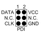
Horloge
Relevé de l'horloge (PDI CLK)
On observe des oscillations. Ces dernières ont un dépassement de 20%
La fréquence minimale de programmation est de 10 KHZ . Nous sommes à la fréquence de 2 Mhz
Données
Relevé de la trame de données (PDI DATA)
Fréquence de la trame : 2.7174 Hz
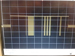
Programmation à l'aide du mkII
Matériel nécessaire
-Pc avec AVR Studio
-Connecteur MKII
-Atxmega
-Led
-Résistance
Schéma d'installation :
AVR Studio
Le logiciel AVR Studio est disponible à l'adresse suivante :http://www.atmel.com/microsite/avr_studio_5/
Exemple
Clignotement d'une Led :
Code C :
- include <avr/io.h>
int main(void)
{
int i;
PORTB_DIR= 0XFF;
while(1)
{
PORTB_OUT= 0x00;
for(i=0;i<=10000;i++);
PORTB_OUT= 0xFF;
for(i=0;i<=10000;i++);
}
}
Relevé du résultat :
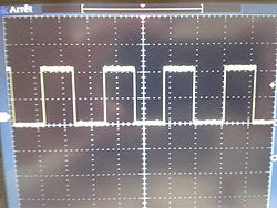
Programmation via une Raspberry
Matériel nécessaire
Le matériel nécessaire pour programmer les cartes avec une Raspberry est le suivant :
- Pc
- Microcontrôleur : Atxmega par exemple
- Platine d'expérimentation
- Led
- Résistance
Bibliothèque
Les bibliothèques suivantes sont nécessaire pour reprogrammer en PDI :
- gcc-avr
- binutils-avr
- https://github.com/DiUS/xmega-pdi-pi2
- build-essential
- g ++
-libcm2835
Installation de la libcm2835
wget http://67.192.60.197/mikem/bcm2835/bcm2835-1.46.tar.gz
tar xvfz bcm2835-1.4.6.tar.gz;
cd bcm2835-1.46;
./configure;
make;
sudo make install
Connexion du Pdi sur la Raspbrerry
Le PDI sera connecté sur les broches suivantes de la Raspberry :
-broche 1 : 3.3V
-broche 25 : GND
-broche 16 : PDI_Data
-broche 18 : PDI_clk
Correspondance entre les broches et les gpio :
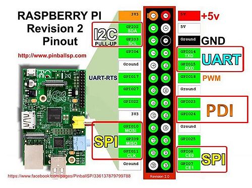
Programmation
Un exemple de programmation du microcontrôleur via le PDI
- Compilation du fichier C
$ avr-gcc -g -Os -mmcu=atxmega64a1 -c demo.c
- Génération du fichier .hex
$ avr-gcc -g -mmcu=atxmega64a1 -o demo.elf demo.o
$ avr-objcopy -j .text -j .data -O ihex demo.elf demo.hex
- Transfert du fichier .hex à la racine de la raspberry
scp nom_fichier.hex pi@adresse_raspberry:~/
- Transfert de la raspberry vers l'atxmega
sudo ./pdi -c (Numéro de la GBIO de la Clock) -d (Numéro de la GBIO de la Data) -a override base address (note: PDI address space) - F Nom du fichier.hex
Exemple
Clignotement d'une Led :
Code C :
- include <avr/io.h>
int main (void)
{
int i;
PORTB.DIR= 1;
while(1)
{
PORTB.OUT=0;
for(i=0;i<=10000;i++);
PORTB.OUT= 1;
for(i=0;i<=10000;i++);
}
}
Fichier hex généré pour l 'atxmega
Extrait du fichier hex :
- 1001F0000C94080111241FBECFEFDFE2DEBFCDBF9C
- 1002000018BE19BE1ABE1BBE0E940A010C94120130
- 100210000C9400008FEF80932006109224068093A8
- 080220002406FBCFF894FFCF88
- 00000001FF
Résultat :
Programmation via un microcontrôleur
Le matériel nécessaire pour programmer les cartes avec un microcontrôleur est le suivant :
-2 microcontrôleur de type Atxmega
-Platine d'expérimentation
-Led
-Résistance
Schéma de connexion entre les microcontrôleurs :
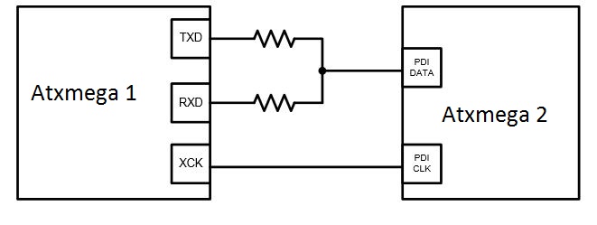
Atmel Software Framework (ASF)
Présentation
Extrait issue du site Atmel :
The Atmel® Software Framework (ASF) is a MCU software library providing a large collection of embedded software for Atmel flash MCUs: megaAVR, AVR XMEGA, AVR UC3 and SAM devices.
It simplifies the usage of microcontrollers, providing an abstraction to the hardware and high-value middlewares
ASF is designed to be used for evaluation, prototyping, design and production phases
ASF is integrated in the Atmel Studio IDE with a graphical user interface or available as standalone for GCC, IAR compilers
ASF can be downloaded for free
Access the ASF documentation.
Note: ASF in Atmel Studio does not require a specific download. Use Atmel Studio Extension Manager (Tools->Extension Manager) or visit Atmel Gallery to update ASF in Atmel Studio.
Le site se situe à l'adresse suivante : asf framework
Capture d'écran du site :
USART
Format de la trame
Le projet P10 souhaite que la trame issue de l'USART soit la suivante :
| Mode de transmission ( S : USART ; U : USB ; R : Radio) |
ID | Numéro de la carte fille |
Numéro de la carte petite fille |
Data |
Exemple :
| S | 005 | 8 | 2 | 255 |
| Data transmise via l'uart | Noeud 5 | Carte fille 8 | Carte fille 2 | Mesure d'une témperature |
Implantation
Fonctionnement durant la procédure de test
Commande hub USART (carte A)
| Action | Envoi | Reception |
| Récupérer l'ensemble des trames du noeud | A | -Trame B -Trame C -Trame D -Trame E -Trame F -Trame G -Trame H -Trame I |
| Récupération partiel sous réserve de validation | ||
| Récupérer la trame de la carte B | B | Trame B |
| Récupérer la trame de la carte C | C | Trame C |
| Récupérer la trame de la carte D | D | Trame D |
| Récupérer la trame de la carte E | E | Trame E |
| Récupérer la trame de la carte F | F | Trame F |
| Récupérer la trame de la carte G | G | Trame G |
| Récupérer la trame de la carte H | H | Trame H |
| Récupérer la trame de la carte I | I | Trame I |
Génération de trame aléatoire
Code : Fichier:Generateur trame aleatoire.zip
Le fichier main (usart_example.c) se trouve dans le dossier suivant :
generateur_trame_aleatoire\USART_EXAMPLE2\src\config\usart_example.c
Pour régler la vitesse de l'usb et de l'uart il faut modifier le fichier suivant :
generateur_trame_aleatoire\USART_EXAMPLE2\src\config\conf_usart_example.h
Modification de la vitesse pour la liaisons série : #define USART_SERIAL_J1_BAUDRATE 9600
Modification de la vitesse pour la liaisons USB : #define USART_SERIAL_J4_BAUDRATE 115200
Simulation d'une trame donnée
Code : Fichier:Generateur trame donne.zip
Le fichier main (usart_example.c) se trouve dans le dossier suivant :
generateur_trame_donne\USART_EXAMPLE2\src\config\usart_example.c
Pour régler la vitesse de l'usb et de l'uart il faut modifier le fichier suivant :
generateur_trame_donne\USART_EXAMPLE2\src\config\conf_usart_example.h
Modification de la vitesse pour la liaisons série : #define USART_SERIAL_J1_BAUDRATE 9600
Modification de la vitesse pour la liaisons USB : #define USART_SERIAL_J4_BAUDRATE 115200
USB
Présentation de la board EVB-USB2517
The SMSC USB2517 MultiTRAK™ is a Low-Power Full-Featured High-Speed USB 2.0 compliant hub with seven down-stream ports. The EVB-USB2517 Evaluation Board demonstrates a standalone application for the hub with advanced power saving options and configurable port assignments. It is a demonstration and low-cost evaluation platform that robustly demonstrates the unique features of this device using a low-cost PCB implementation with individual port power control. The EVB-USB2517 is designed for a low cost, power efficient implementation of a High-Speed USB Hub that supports internal default hub configurations as well as optionally supports an external EERPOM configuration. This evaluation platform supports a red LED indicator for the High-Speed hub state as well as standard USB Amber/Green LED indicators for operational state indication.
Source : Microship
Implantations
Normalisation électrique
| Couleur | Fonction associée |
| Jaune | PDI (Data et Clock ) |
| Rouge | + 3.3 V |
| Bleu | Masse |
| Vert/Jaune | UART |
Configuration des Raspberry
Raspberry PI
Mapping de connection du noeud :
| PDI_DATA | PDI_CLOCK | Action | |||
| Broche | Gpio | Broche | Gpio | ||
| Carte A (Hub USART) | 16 | 23 | 18 | 24 | Reprogrammez le HUB USART en pdi Il faut désactiver l'interface SPI de la raspberry |
| Carte fille B (1) | 15 | 22 | 13 | 27 | Reprogrammez la carte fille B en pdi |
| Carte fille C (2) | 19 | 10 | 21 | 9 | Reprogrammez la carte fille C en pdi |
| Carte fille D (3) | 11 | 17 | 12 | 18 | Reprogrammez la carte fille D en pdi |
| Carte fille E (4) | 7 | 4 | 22 | 25 | Reprogrammez la carte fille E en pdi |
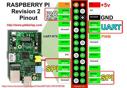
Raspberry PI 2
| PDI_DATA | PDI_CLOCK | Action | |||
| Broche | Gpio | Broche | Gpio | ||
| Carte A (Hub USART) | 11 | 17 | 13 | 27 | Reprogrammez le HUB USART en pdi Il faut désactiver l'interface SPI de la raspberry |
| Carte fille B(1) | 12 | 18 | 22 | 25 | Reprogrammez la carte fille B en pdi |
| Carte fille C (2) | 33 | 13 | 35 | 19 | Reprogrammez la carte fille C en pdi |
| Carte fille D (3) | 16 | 23 | 18 | 24 | Reprogrammez la carte fille D en pdi |
| Carte fille E (4) | 36 | 16 | 38 | 20 | Reprogrammez la carte fille E en pdi |
| Carte fille F (5) | 15 | 22 | 37 | 26 | Reprogrammez la carte fille F en pdi |
| Carte fille G (6) | 32 | 12 | 40 | 21 | Reprogrammez la carte fille G en pdi |
| Carte fille H (7) | 19 | 10 | 21 | 9 | Reprogrammez la carte fille H en pdi |
| Carte fille I (8) | 29 | 5 | 31 | 6 | Reprogrammez la carte fille I en pdi |
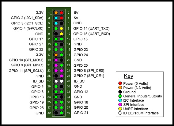
Exemple de capteur
Mesure de la température
Ce type de capteur utilise le convertisseur analogique numérique du microcontroleur. Les paramétres à configurés seront les suivantes :
* Quantum

* Plage de mesure

* Registre
Ce capteur à les caractéristiques suivantes :
Fournisseur : Conrard
Référence :Capteur de température numérique TSIC506 boîtier TO 92 B & B Thermotechnik TSIC506-TO92
Plage de mesure :-10 C - 60C
Tension d'alimentation :3-5.5V
Précision : +/- 0.1 C
Consommation : 30 - 60 µA
Implantation
Les cartes Xplained mise à notre disposition sont équipées de capteur de température.Nous avons implanté un pseudo noeud de capteur dans la salle E306 le 1 février
Code : Fichier:Capteur temperature.zip
Le fichier main (adc_example1_gfx.c) se trouve dans le dossier suivant :
capteur_temperature\src\adc_example1_gfx.c
Pour régler la vitesse de l'usb et de l'uart il faut modifier le fichier suivant :
capteur_temperature\src\config\conf_usart_spi.h
Modification de la vitesse pour la liaisons série : #define USART_SERIAL_J1_BAUDRATE 9600
Modification de la vitesse pour la liaisons USB : #define USART_SERIAL_J4_BAUDRATE 115200
Mesure du volume sonore
La mesure d'un volume sonore se réalise par la transformation d'un vibration en un signal éléctrique.Afin de pouvoir l'exploiter il faudra
le connecté sur le convertisseur analogique numérique du microcontroleur.Les paramétres à configurés seront les suivantes :
* Quantum

* Registre
Ce capteur à les caractéristiques suivantes :
Fournisseur : Zartronic.fr
Référence :Capteur Sonore Analogique
Tension d'alimentation :5V
Exemple de courbe généré par le générateur de trame
Mesure de la luminosité
La mesure de la luminosité s'effectue avec l'aide d'un photo-transistor. Le photo-tansistor fera varier une résistance. On peut mesurer sa tension
a ses bornes. Cette tension étant trés faible il est nécessaire d'avoir un amplificateur en sortie. La tension sera exploitable par le
convertisseur analogique numérique du microcontroleur.Les paramétres à configurés seront les suivantes :
* Quantum

* Registre
Ce capteur à les caractéristiques suivantes :
Fournisseur : Conrard
Référence :Photo-résistance FW200
Composition d'un noeud
La carte mère
Composition
La carte mère est constitué de :
- une carte raspberry pi
- un hub USART (matérialisé ici par une carte XMega-A3BUX Xplained)
- un hub USB
| Amont (Réseaux) | ||
| Hub UART | Rapsberry | Hub USB |
| Aval (Vers carte fille) | ||
Fonctions
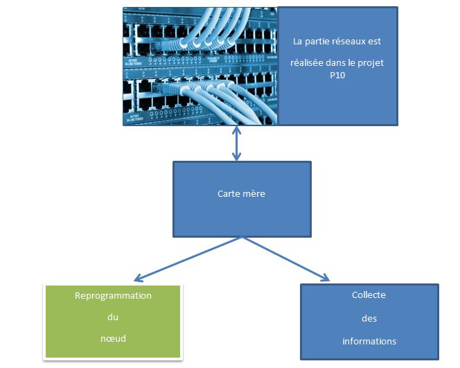
Connexions
| Ancienne appellation | Nouvelle appellation |
| Carte fille 1 | Carte B |
| Carte fille 2 | Carte C |
| Carte fille 3 | Carte D |
| Carte fille 4 | Carte E |
| Carte fille 5 | Carte F |
| Carte fille 6 | Carte G |
| Carte fille 7 | Carte H |
| Carte fille 8 | Carte I |
La carte fille
Composition
La carte fille est constituée d'une carte Xplained
| Amont (Vers Raspberry ) |
| Aval (Vers carte petite fille) |
Fonction
Les fonctions de la carte sont :
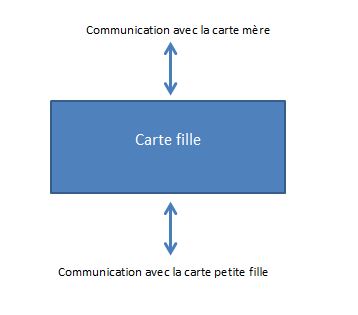
Connexion
| Données | Programmation | |||||||
| USART | USB | PDI | SPI / I2C ... | |||||
| Amont (vers la raspberry) |
Aval (vers les capteurs) |
Amont (vers la raspberry) |
Aval (vers les capteurs) |
Amont (vers la raspberry) |
Aval (vers les capteurs) |
Amont (vers la raspberry) |
Aval (vers les capteurs) |
|
| Carte B | Carte A (Interface ttyUSB0) |
- Carte B1 - Carte B2 |
Hub USB (Interface ttyACM0) |
- | Carte mère (Voir configuration Rasbperry) |
- | - | - Carte B1 - Carte B2 |
| Carte C | Carte A (Interface ttyUSB1) |
- Carte C1 - Carte C2 |
Hub USB (Interface ttyACM1) |
- | Carte mère (Voir configuration Rasbperry) |
- | - | - Carte C1 - Carte C2 |
| Carte D | Carte A (Interface ttyUSB2) |
- Carte D1 - Carte D2 |
Hub USB (Interface ttyACM2) |
- | Carte mère (Voir configuration Rasbperry) |
- | - | - Carte D1 - Carte D2 |
| Carte E | Carte A (Interface ttyUSB3) |
- Carte E1 - Carte E2 |
Hub USB (Interface ttyACM3) |
- | Carte mère (Voir configuration Rasbperry) |
- | - | - Carte E1 - Carte E2 |
| Carte F | Carte A (Interface ttyUSB4) |
- Carte F1 - Carte F2 |
Hub USB (Interface ttyACM4) |
- | Carte mère (Voir configuration Rasbperry) |
- | - | - Carte F1 - Carte F2 |
| Carte G | Carte A (Interface ttyUSB5) |
- Carte G1 - Carte G2 |
Hub USB (Interface ttyACM5) |
- | Carte mère (Voir configuration Rasbperry) |
- | - | - Carte G1 - Carte G2 |
| Carte H | Carte A (Interface ttyUSB6) |
- Carte H1 - Carte H2 |
Hub USB (Interface ttyACM6) |
- | Carte mère (Voir configuration Rasbperry) |
- | - | - Carte H1 - Carte H2 |
| Carte I | Carte A (Interface ttyUSB7) |
- Carte I1 - Carte I2 |
Hub USB (Interface ttyACM7) |
- | Carte mère (Voir configuration Rasbperry) |
- | - | - Carte I1 - Carte I2 |
La carte petite fille
Présentation
Cette carte ne sera pas présente dans le nœud. Le générateur de trame nous simulera les informations remontées par cette dernière .
Fonction
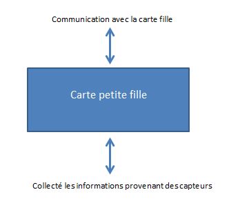
Connexion
Dénomination des cartes :
| Carte parent | Ancienne appellation | Nouvelle appellation |
| Carte B (Ex carte fille 1) | Carte Petite fille 1 | Carte B1 |
| Carte Petite fille 2 | Carte B2 | |
| Carte C (Ex carte fille 2) | Carte Petite fille 1 | Carte C1 |
| Carte Petite fille 2 | Carte C2 | |
| Carte D (Ex carte fille 3) | Carte Petite fille 1 | Carte D1 |
| Carte Petite fille 2 | Carte D2 | |
| Carte E (Ex carte fille 4) | Carte Petite fille 1 | Carte E1 |
| Carte Petite fille 2 | Carte E2 | |
| Carte F(Ex carte fille 5) | Carte Petite fille 1 | Carte F1 |
| Carte Petite fille 2 | Carte F2 | |
| Carte G (Ex carte fille 6) | Carte Petite fille 1 | Carte G1 |
| Carte Petite fille 2 | Carte G2 | |
| Carte H (Ex carte fille 7) | Carte Petite fille 1 | Carte H1 |
| Carte Petite fille 2 | Carte H2 | |
| Carte I (Ex carte fille 8) | Carte Petite fille 1 | Carte I1 |
| Carte Petite fille 2 | Carte I2 |
| Données | Programmation | ||||||||
| USART | USB | Type de données |
PDI | SPI / I2C ... | |||||
| Amont (vers la raspberry) |
Aval (vers les capteurs) |
Amont (vers la raspberry) |
Aval (vers les capteurs) |
Amont (vers la raspberry) |
Aval (vers les capteurs) |
Amont (vers la raspberry) |
Aval (vers les capteurs) |
||
| Carte B1 | Carte B | - | Carte B | - | Température | - | - | Carte B | - |
| Carte B2 | Carte B | - | Carte B | - | - | - | Carte B | - | |
| Carte C1 | Carte C | - | Carte C | - | Température | - | - | Carte C | - |
| Carte C2 | Carte C | - | Carte C | - | - | - | Carte C | - | |
| Carte D1 | Carte D | - | Carte C | - | - | - | Carte D | - | |
| Carte D2 | Carte D | - | Carte C | - | - | - | Carte D | - | |
| Carte E1 | Carte E | - | Carte E | - | - | - | Carte E | - | |
| Carte E2 | Carte E | - | Carte E | - | - | - | Carte E | - | |
| Carte F1 | Carte F | - | Carte F | - | - | - | Carte F | - | |
| Carte F2 | Carte F | - | Carte F | - | - | - | Carte F | - | |
| Carte G1 | Carte G | - | Carte G | - | - | - | Carte G | - | |
| Carte G2 | Carte G | - | Carte G | - | - | - | Carte G | - | |
| Carte H1 | Carte H | - | Carte H | - | - | - | Carte H | - | |
| Carte H2 | Carte H | - | Carte H | - | - | - | Carte H | - | |
| Carte I1 | Carte I | - | Carte I | - | - | - | Carte I | - | |
| Carte I2 | Carte I | - | Carte I | - | - | - | Carte I | - | |
Interface web
Adresse du site de présentation : lien
Page Home :
Page Setting :
Plateforme intermédiaire
Schéma
Implantation
Information
| Programmation | ||
| PDI_DATA | PDI_Clk | |
| Carte A | GPIO 23 | GPIO 24 |
| Carte B | GPIO 22 | GPIO 27 |
| Vitesse de transfert | ||
| USART | 9 600 - 115 200 | |
| USB | - | |
| Configuration | ||
| Amont (vers la raspberry) |
Aval (vers les capteurs ) |
|
| Raspberry | Réseau - Projet P10 | Carte A Carte USB |
| Carte A | Raspberry | Carte B |
| Carte B | -Carte A - Carte USB |
NC |
| Carte USB | Raspberry | Carte B |
| Connections | ||
| Carte Xmega-A3BU | ||
| Port J1 | Port J2 | |
| Carte A | Broche Rx et Tx USART vers la Raspberry |
Broche Rx et Tx USART vers la carte B |
| Carte B | Broche Rx et Tx USART vers la carte A |
Broche Rx et Tx USART vers la carte USB |
| Raspberry | ||
| Broche | ||
| 1 | Alimentation de la carte A | |
| 8 | USART TX | |
| 10 | USART RX | |
| 13 | PDI Clk carte B | |
| 14 | GND Carte A | |
| 15 | PDI Data Carte B | |
| 16 | PDI Data carte A | |
| 17 | Alimentation Carte B | |
| 18 | PDI Clock Carte A | |
| 25 | GND Carte B | |
| Câble de connexion | ||
| Couleur | ||
| Rouge | +3.3 V | |
| Bleu | GND | |
| Jaune | PDI | |
| Vert /Jaune | UART | |
Plateforme
Nœud 1
Composition
Le nœud 1 est constitué de :
carte mère :
-1 Raspberry PI2
-2 cartes EVB-USB2517
carte fille :
-6 cartes d'essai Xplained
carte petite fille :
Ces cartes ne sont pas implantées sur le nœud. On simulera les capteurs.
Implantation
Information
| PDI_DATA | PDI_CLOCK | |||
| Broche | Gpio | Broche | Gpio | |
| Carte A | 11 | 17 | 13 | 27 |
| Carte B | 12 | 18 | 22 | 25 |
| Carte C | 33 | 13 | 35 | 19 |
| Carte D | 16 | 23 | 18 | 24 |
| Carte E | 36 | 16 | 38 | 20 |
| Carte F | 15 | 22 | 37 | 26 |
| Interface UART | ||
| Carte A | ttyUSB0 | |
| Carte B | ttyUSB1 | |
| Carte C | ttyUSB2 | |
| Carte D | ttyUSB3 | |
| Carte E | ttyUSB4 | |
| Carte F | ttyUSB5 | |
| Vitesse de transfert | ||
| USART | 115 200 | |
| USB | - | |
| Câble de connexion | ||
| Couleur | ||
| Rouge | +3.3 V | |
| Bleu | GND | |
| Jaune | PDI | |
Nœud 2
Composition
Le nœud 2 est constitué de :
carte mère :
-1 Raspberry PI
-1 carte EVB-USB2517
-1 hub usb
-1 boutons poussoirs pour effectuer une remise à zéro
-1 dispositif de visualisation
| Etat | Action | |
| Led de programmation | Eteinte | Pas de remise à zéro en cours ni demandé |
| Clignotante | / | |
| Allumé | Demande de remise à zéro et Remise à zéro en cours | |
| Led de remise à zéro | Eteinte | Pas de programmation en cours |
| Clignotante | Programmation en cours | |
| Allumé | Erreur de programmation |
carte fille :
-4 cartes d'essai Xplained
carte petite fille :
Ces cartes ne sont pas implantées sur le nœud. On simulera les capteurs.
Implantation
| Sans liaison USB | Avec liaison USB |
Information
| Programmation | ||||
| PDI_DATA | PDI_CLOCK | |||
| Broche | Gpio | Broche | Gpio | |
| Carte A | 16 | 23 | 18 | 24 |
| Carte B | 15 | 22 | 13 | 27 |
| Carte C | 19 | 10 | 21 | 9 |
| Carte D | 11 | 17 | 12 | 18 |
| Interface UART | ||
| Carte A | ttyUSB0 | |
| Carte B | ttyUSB1 | |
| Carte C | ttyUSB2 | |
| Carte D | ttyUSB3 | |
| Interface USB | ||
| Carte A | ttyACM0 | |
| Carte B | ttyACM1 | |
| Carte C | ttyACM2 | |
| Carte D | ttyACM3 | |
| Vitesse de transfert | ||
| USART | 115 200 baud | |
| USB | 3.5 Mbits | |
| Câble de connexion | ||
| Couleur | ||
| Rouge | +3.3 V | |
| Bleu | GND | |
| Jaune | PDI | |
Code source
| Procédure | Fichier | Nom de l'exécutable | Action réalisé par le programme | Note |
| Initialisation de la Raspberry | Média:Init.zip | ./dem_noeud ou dem_noeud* | Initialisation des GPIO Exécution du programme de la gestion du boutons poussoir en tache de fond |
Ce code est à utilisé a chaque démarrage de la Raspberry |
| Remise a zéro | Média:Remise_à_zéro.zip | ./raz ou raz* | Mettre les broches du PDI Clock à l'état bas | Ce programme est appellé par un appuie sur le bouton poussoir |
| Gestion du bouton poussoir | Média:Gestion_du_boutons_poussoir.zip | ./bp ou bp* | Ce programme est lancé en tache de fond Il est lancé au démarrage du noeud Lorsque l'on appuie sur le boutons on appelle le programme RAZ qui remetra l'ensemble du noeud à zéro |
Ce programme est appellé par le programme du boutons poussoirs |
| Programmation du noeud | Média:Programmation.zip | ./programmer ou programmer* | Reprogrammation du noeud suivant le nombre d'argument |
- ces commandes sont possible si on crée un path
Code d'exemple pour l'UART:Média:UART.zip
Code d'exemple pour l'USB :Média:USB.zip
Vous trouvez l'ensemble des codes dans ce fichier :Média:Lilliad_plateforme_code_source.zip
Réalisation d'un support de présentation
Procédure et historique
Mode de programmation
Programmation simple
Ce câblage est le plus utilisé sur le nœud car on reprogramme une carte avec un fichier.
Schéma :
Programmation Multiple
Ce cablage nous permet de connecter plusieurs carte ensemble afin d'utiliser qu'un seul programme
Procédure pour programmer un nœud
La commande pour programmer un nœud est la suivante : programmer
La commande a besoin d'argument pour reprogrammé le noeud. Ces arguments sont des fichier .hex
En fonction du nombre d'argument le programme va réalisé les programmations suivantes :
| Nombre d'argument | Action |
| 1 | Reprogrammation de l’ensemble du nœud Reprogrammation d’une carte |
| 2 | Reprogrammation de la carte A Reprogrammation de la carte B |
| 3 | Reprogrammation de la carte A Reprogrammation de la carte B Reprogrammation de la carte C |
| 4 | Reprogrammation de la carte A Reprogrammation de la carte B Reprogrammation de la carte C Reprogrammation de la carte D |
| 5 | Reprogrammation de la carte A Reprogrammation de la carte B Reprogrammation de la carte C Reprogrammation de la carte D Reprogrammation de la carte E |
| 6 | Reprogrammation de la carte A Reprogrammation de la carte B Reprogrammation de la carte C Reprogrammation de la carte D Reprogrammation de la carte E Reprogrammation de la carte F |
| 7 | Reprogrammation de la carte A Reprogrammation de la carte B Reprogrammation de la carte C Reprogrammation de la carte D Reprogrammation de la carte E Reprogrammation de la carte F Reprogrammation de la carte G |
| 8 | Reprogrammation de la carte A Reprogrammation de la carte B Reprogrammation de la carte C Reprogrammation de la carte D Reprogrammation de la carte E Reprogrammation de la carte F Reprogrammation de la carte G Reprogrammation de la carte H |
| 9 et + | Reprogrammation de la carte A Reprogrammation de la carte B Reprogrammation de la carte C Reprogrammation de la carte D Reprogrammation de la carte E Reprogrammation de la carte F Reprogrammation de la carte G Reprogrammation de la carte H Reprogrammation de la carte I |
Capture d'écran du programme:
Procédure pour remettre à zéro un nœud
Pour remettre à zéro l'ensemble du nœud il faut appuyer sur le boutons poussoirs pendant 5 secondes. Ensuite la raspberry remettra le nœud à zéro via le programme RAZ. Capture d'écran de la remise à zéro.
A cela s'ajoute une LED qui s'allume dés que la demande du boutons a été prise en compte et ceux jusqu’à la fin de la procédure de la remise à zéro.
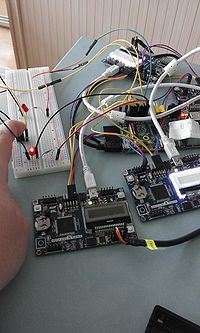
|
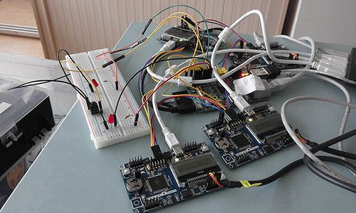
|
Procédure de démarrage
Cette procédure doit être exécuter à chaque démarrage de la Raspberry. Cette procédure initialise les GPIO, remet à zéro le nœud et lance en tache de fond la gestion du boutons poussoirs
Capture d'écran de la procédure de démarrage:
Historique des bug sur la plateforme
-25 janvier
Programmation (PDI ) : Error : failed to rewrite at the adress 4096 -> Reprogrammation effectué
8 tentative avant la reprogrammation de la flash
- 3 février
Programmation (PDI ) : Error : failed to rewrite at the adress 0 sur les GPIO 5 et 6 -> changement du mapping de la raspberry
- 3 février au 9 février
aucun problème n'a été constaté . Des tests sont effectués régulièrement sur la reprogrammation des cartes et sur la lecture des données
- 9 février 16:00
Le nœud 1 est inaccessible en attente de la modifications du réseau par le projet P10
- 9 février 16:00 - 16 février 16:00
Problème de configuration réseaux. Les cartes sont ré-configurés en local. En dehors des heures de projet les nœuds sont hors tension
- 10 février
Aucun test de remonter de donné n a pu être réalisé .Des tests en local ont effectué après une journée de non alimentation des nœuds. Il s'est relevé l'erreur suivante :Error Fail to rewrite at the adres xxxx.
Recherche du problème
- 11 février
Des tests en local sont en cours afin de trouver une procédure de redémarrage.Les premiers semble aboutir. Le noeud a été mis au repose pendant une journée afin de recommencer la procédure
- 12 février
Suite des tests de la procédure de redémarrage
- Programmation (PDI ) : Error : failed to rewrite at the adress 8704 -> Reprogrammation effectué
- RAZ : Error :failed to perform chip erase ->Opération effectué
Taux de réussite des tests : 7/10
La procédure de démarrage est quasi opérationnel . Les prochains tests nous permettrons de fiabiliser la procédure
- 15 février
Procédure de redémarrage fiabiliser. Nous sommes en mesure de reprogrammer l'ensemble du nœud avec zéro erreur
Nouvelle procédure de programmation mise en place. Les résultats est de 100 % de réussite a chaque programmation , chaque redémarrage quelque soit le programme
- 16 février
Déploiement de la nouvelle méthode de programmation sur les deux noeuds. Le nœud 2 est opérationnel pour effectuer une démonstration lors de la soutenance. Le réseaux a été rétabli à 16h
- 17 février
Cette journée a été consacrée à la prise en main de la plateforme existante par les encadrants.Aucun problème constaté sur la plateforme
- 18 février
Ajout de la fonction Remise à zéro du nœud par simple appui sur le boutons poussoirs et de la procédure de démarrage. Arrêt temporaire de développement de la plateforme
- 19 février - 23 février
Rédactions des livrables de fin de projet
- 22 février
Tournage de la vidéo
- 25 février
Rendu des codes sources. Fin du projet
Évolution vers un nœud implantable dans un lieux public
Mesure de l' énergie
Implantée sur la carte mère la mesure de l'énergie nous indiquera la consommation du nœud. Cette dernière sera mesurer à l'aide de convertisseurs analogique-numérique
La consomation ne peut pas être mesuré directement. Pour cela on va utiliser une résistance de quelque ohms.La façon la plus simple est de connaitre les éléments suivants :
-la valeur de la résistance
-la tension
Formule à utiliser pour estimer la puissance:
On pose :
Mr : valeur issue du CAN
Ir: Estimation du courant dans la résistance
U : tension d'alimentation
Afin d'estimer le courant de la résistance il faut convertir Mr suivant la courbe du CAN. Cette dernière est linéaire.
Un fois la valeur convertie on aura à appliquer la formule suivante : P=U*Ir
Modification de la trame de donnée
La trame utilisé lors des différents essai ne correspond pas totalement aux besoins de l'utilisateur. C'est pour cette raison que nous allons remplacé la trame par celle-ci:
| En tête | |||||||
| Mode (Full ou simple) |
Mode de transmission ( S : USART ; U : USB ; R : Radio) |
ID | |||||
| Corps | |||||||
| Numéro de la carte fille | Data de la carte petite fille 1 |
Data de la carte petite fille 2 |
|||||
Alimentation externe du nœud
Actuellement nous alimentons le nœud via la raspberry. L’idée est de passé sur une alimentation secteur 230 V.
Remplacement des cartes d'essais
Carte mère
On conserve la Raspberry ainsi que l’hub USB. On supprimera les câbles série USB par une carte dédiée à l’UART.
Cette carte sera composée d’un ATxmega32A4U qui a les caractéristiques suivantes :
- Reprogrammation en PDI
- 5 ports USART
- CAN
- USB
- 7 port SPI
- 2 portI2C
Pour plus d'informations cliquez ici
Pour les bessoins du noeud nous avons décider de mettre 2 ATxmega32A4U . Ce choix nous permet d'avoir un demi noeud toujours opérationnel. De plus nous avons la possibilité de reprogrammer les deux cartes avec le même fichier .
Exemple de configuration des ports
| Fonction | Port | Numéro Pin | Pin Fonctions | Numéro Pin | Pin Fonctions | Carte |
| Reprogrammation | ||||||
| PDI | R | 35 | Clock | 34 | Data | - |
| Carte Microcontrôleur numéro 1 | ||||||
| USART 1 | C | 12 | Rx | 13 | Tx | Liaison vers la Raspberry |
| USART 2 | C | 16 | Rx | 17 | Tx | Carte B |
| USART 3 | D | 22 | Rx | 23 | Tx | Carte C |
| USART 4 | D | 26 | Rx | 27 | Tx | Carte D |
| USART 5 | E | 32 | Rx | 33 | Tx | Carte E |
| Carte Microcontrôleur numéro 2 | ||||||
| USART 1 | C | 12 | Rx | 13 | Tx | Liaison vers la Raspberry |
| USART 2 | C | 16 | Rx | 17 | Tx | Carte F |
| USART 3 | D | 22 | Rx | 23 | Tx | Carte G |
| USART 4 | D | 26 | Rx | 27 | Tx | Carte H |
| USART 5 | E | 32 | Rx | 33 | Tx | Carte I |
Schéma de la carte mère :
Le (1) nous montre le remplacements des cartes.Cette carte pourra mesuré de l’énergie d'un demi nœud
Carte fille
La carte Xplained sera remplacée par un ATxmega256C3 qui a les caractéristiques suivantes :
- Reprogrammation en PDI
- 3 ports USART
- CAN
- USB
- 5 port SPI
- 2 portI2C
Pour plus d'informations cliquez ici
Exemple de configuration des ports
| Fonction | Port | Numéro Pin | Pin Fonctions | Numéro Pin | Pin Fonctions | Numéro Pin | Pin Fonctions | Numéro Pin | Pin Fonctions |
| Reprogrammation | |||||||||
| PDI | R | 57 | Clock | 56 | Data | / | |||
| Connexion pour la carte petite fille 1 | |||||||||
| USART | C | 18 | Rx | 19 | Tx | / | |||
| I2C | C | 16 | SDA | 17 | SCL | / | |||
| SPI | C | 20 | /(SS) | 21 | MOSI | 22 | MISO | 23 | SCK |
| Connexion pour la carte petite fille 2 | |||||||||
| USART | E | 38 | Rx | 39 | Tx | / | |||
| I2C | E | 36 | SDA | 37 | SCL | / | |||
| SPI | D | 30 | /(SS) | 31 | MOSI | 32 | MISO | 33 | SCK |
Carte petite fille
Actuellement nous fonctionnons avec un générateur de trame il sera remplacé par une carte STM32F4
Les différents changements nous conduirons a ce schéma :
Légende :
| Couleur | Fonction associés |
| Violet | I2C |
| Bordeaux | SPI |
| Orange | UART |
| Noir | Alimentation |
| Vert | PDI |
| Bleu | USB |
| Rouge | PDI + USB + UART |
La sélection des microcontrôleurs est donnée à titre d'exemple. Vous avez la possibilité de choisir vôtre microcontrôleur en utilisant l’outil de sélection de chez Atmel qui se trouve ici
Avancement du projet
Dans cette section vous trouverez une vue de l'avancement du projet. Cette section doit être interactive.
Problème rencontrées
| Bloquant | En voie de résolution | Résolu | |
| ASF de atmel | Développé sur Atmel Studio (Window) | ||
| compilation des fichiers exemple de l'usart disponible sur l'asf sous debian | les fichiers sont compilé sous Windows et ensuite on envoie le .hex généré sur la raspberry | ||
| saturation de la mémoire flash de la board (Erreur de type : Error failed to rewrite at the adress 2048) | Il faut mettre une alimentation stabilisée en plus pour ne plus avoir ce problème et espacer le temps entre chaque reprogrammation | ||
| Liasion série sur la raspberry ne fonctionne pas pour remonter les données | Mr REDON m'a aidé à résoudre ce problème |
A faire
| A faire | En cours | Terminé | |
| Reconfiguration en pdi des cartes via l'usart | Cette partie sera traité dans les évolutions du noeud mais pas testé | ||
| Mise en place de la liaison USB | Carte mise en place sur le nœud |
||
| USART | Un code d'essai est opérationnelle. Nous somme en mesure de remonter plusieurs trame de données à la raspberry | ||
| Reprogrammation des cartes d'exemples en PDI | La reprogrammation en PDI est opérationnelle. Cependant quelque résidu nous pose problèmes |
Matériel supplémentaire
5 duplicateurs de ports USB
3 alim 5V / 15W
3 câbles pour alim
3 câbles FTDI intégrés
8 XMEGA-A3BU Xplained

