P5 IOT 2017
Sommaire
- 1 Présentation du sujet
- 2 Réalisation
- 2.1 Matériel utilisé
- 2.2 Suivi de réalisation
- 2.3 Détail du travail de la première séance
- 2.4 Détail du travail de la deuxième séance
- 2.5 Détail du travail de la troisième séance
- 2.6 Détail du travail de la quatrième séance
- 2.7 Détail du travail de la cinquième séance
- 2.8 Détail du travail de la sixième séance
- 3 Rendu
Présentation du sujet
Contexte
Nous effectuons ce projet dans le cadre du module internet des objets (Internet of things).
L'objectif de ce module est de créer l'objet connecté de notre choix.
Nous avons donc choisi de créer un objet en rapport avec la sécurité routière: le système Safe&Drive.
Description du projet
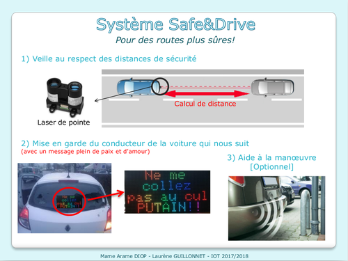
Pour veiller au respect des distances de sécurité, le système S&D va tout d'abord évaluer la distance entre votre voiture et celle qui vous suit.
Grâce au GPS intégré, la distance de sécurité à respecter sera calculée en fonction de votre vitesse de circulation.
Si cette distance de sécurité n'est pas respectée, un message de mise en garde sera affiché sur votre pare-brise arrière à destination du conducteur qui vous suit de trop prêt.
Bien évidemment, ce message ne sera envoyé qu'après confirmation de l'utilisateur depuis l'application mobile du système Safe&Drive.
En mode marche arrière, le système devient une aide à la manœuvre avec une caméra de recul et un détecteur d'obstacle.
Réalisation
Matériel utilisé
- Raspberry Pi
- Arduino Uno
- Arduino Mega2560
- SparkFun GPS Shield
- Adafruit 64x32 RGB LED Matrix - 5mm pitch
- Garmin LIDAR-Lite v3
Suivi de réalisation
| Séance 1 (08/01/2018) | Choix de l'objet + Choix du matériel |
|---|---|
| Séance 2 (09/01/2018) | Circuit shield pour la matrice LED + Test Li-DAR Lite |
| Séance 3 (16/01/2018) | Circuit shield pour la matrice LED + Test du shield GPS |
| Séance 4 (17/01/2018) | Circuit shield pour la matrice LED + Test Shield GPS |
| Séance 5 (22/01/2018) | Soudage circuit shield pour la matrice LED + Test LED Matrix + RaspberryPI + Application mobile |
| Séance 6 (24/01/2018) | Finitions + Resolutions des problèmes + Préparation orale (+poster) |
Détail du travail de la première séance
Pour choisir notre projet nous avons débuté en faisant un pseudo-brainstorming duquel est ressorti 4 projets.
Nous donc dû réduire notre choix à un seul de ces quatre possibilités.
Notre choix final s'est donc porté sur le système Safe&Drive.
Après avoir affiné les divers fonctionnalités de notre projet, nous avons commencé à réunir le matériel dont nous aurions besoin.
Détail du travail de la deuxième séance
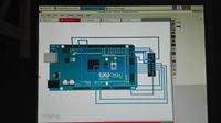
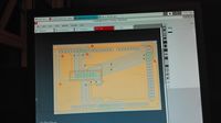
- Début de la création du shield de la matrice de LED qui viendra se positionner sur l’Arduino Mega2560.
- Test du capteur optique LI-DAR Lite et codage du programme pour le calcul de distance.
 LIDARLite Arduino Library
  GetDistanceI2c

  This example shows how to initialize, configure, and read distance from a
  LIDAR-Lite connected over the I2C interface.

  Connections:
  LIDAR-Lite 5 Vdc (red) to Arduino 5v
  LIDAR-Lite I2C SCL (green) to Arduino SCL
  LIDAR-Lite I2C SDA (blue) to Arduino SDA
  LIDAR-Lite Ground (black) to Arduino GND

  (Capacitor recommended to mitigate inrush current when device is enabled)
  680uF capacitor (+) to Arduino 5v
  680uF capacitor (-) to Arduino GND

  See the Operation Manual for wiring diagrams and more information:
  http://www.robotshop.com/media/files/pdf2/pli-06-instruction.pdf

-----------------------------------------------------------------------------------------------------------------------------------------------------------------------------------

#include <Wire.h>
#include <LIDARLite.h>

LIDARLite myLidarLite;
int distance_reelle ;

void setup()
{
  Serial.begin(9600); // Initialize serial connection to display distance readings

  myLidarLite.begin(0, true); // Set configuration to default and I2C to 400 kHz

  myLidarLite.configure(0); // Change this number to try out alternate configurations
}

void loop()
{

  // Take a measurement with receiver bias correction and print to serial terminal
  distance_reelle = (myLidarLite.distance());
  if(distance_reelle < 1)
  {
	Serial.println('O');
  }
  else
  {
	Serial.println('N');
  }
}
Détail du travail de la troisième séance
- Poursuite de la création du circuit (shield) pour la matrice LED.
Cela n'a pas été une tâche facile en raison de la répartition des différentes pâtes dont nous avions besoin et des liaisons à effectuer.
- Test du GPS et codage du programme de calcul de vitesse.
Nous avons rencontré des problèmes avec le GPS, celui-ci ne renvoyait des message d'erreurs "NO GPS DETECTED" ou bien des données nulles du type "Date: 00/00/0000".
Détail du travail de la quatrième séance
- Finition du circuit (shield) pour la matrice LED et envoi de la demande de fabrication
Nous avons rencontré un problème avec le logiciel nous avons donc dû refaire entièrement le circuit, cela nous a pas mal retardé dans notre projet.
- Test du GPS et résolution des problèmes.
Nous avons rencontré beaucoup de problèmes avec le GPS, celui-ci se connectait bien aux satellites mais ne nous renvoyait que des données nulles ou bien un message d'erreur.
Il s'est en faite avéré que selon la position du GPS receiver sur le shield celui-ci affichait ou non les données.
Le problème a donc été résolu. Voici le code:
}

#include <TinyGPS++.h>
#include <SoftwareSerial.h>
#include <Wire.h>
/*
 This example uses software serial and the TinyGPS++ library by Mikal Hart
 Based on TinyGPSPlus/DeviceExample.ino by Mikal Hart
 Modified by acavis
*/

// Choose two Arduino pins to use for software serial
// The GPS Shield uses D2 and D3 by default when in DLINE mode
int RXPin = 50;
int TXPin = 3;

// The Skytaq EM-506 GPS module included in the GPS Shield Kit
// uses 4800 baud by default
int GPSBaud = 4800;

// Create a TinyGPS++ object called "gps"
TinyGPSPlus gps;

// Create a software serial port called "gpsSerial"
SoftwareSerial gpsSerial(RXPin, TXPin);

void setup()
{
  // Start the Arduino hardware serial port at 9600 baud
  Serial.begin(9600);

  // Start the software serial port at the GPS's default baud
  gpsSerial.begin(GPSBaud);

  Serial.println(F("DeviceExample.ino"));
  Serial.println(F("A simple demonstration of TinyGPS++ with an attached GPS module"));
  Serial.print(F("Testing TinyGPS++ library v. ")); Serial.println(TinyGPSPlus::libraryVersion());
  Serial.println(F("by Mikal Hart"));
  Serial.println();

}

void loop()
{
  // This sketch displays information every time a new sentence is correctly encoded.
  while (gpsSerial.available() > 0)
    if (gps.encode(gpsSerial.read()))
      displayInfo();

  // If 5000 milliseconds pass and there are no characters coming in
  // over the software serial port, show a "No GPS detected" error
  if (millis() > 5000 && gps.charsProcessed() < 10)
  {
    Serial.println(F("No GPS detected"));
    while(true);
  }
}

void displayInfo()
{
  Serial.print(F("Speed: "));
  if (gps.speed.isValid())
  {
    Serial.print(gps.speed.kmph(), 6);
  }
  else
  {
    Serial.print(F("INVALID"));
  }


  Serial.println();

  secure_dist = (gps.speed.kmph()/10)*6;
  Serial.print("distance de sécurite (en  m)= ");
  Serial.print(secure_dist);
  Serial.println();

}
Détail du travail de la cinquième séance
- Soudage des barrettes et des ponts sur le circuit pour la Matrice LED (Shield)
- Test de la matrice LED et codage du programme pour l'affichage d'un message personnalisé coloré
Message choisi: Ne me collez pas au cul, PUTAIN!! Voici le code pour l'affichage du message. Celle-ci se fait grâce à un liaison série entre la raspberry Pi (RPI) et la matrice de de LED connectée à l’arduino Mega à travers le shield.
Voici le code pour l'affichage:
/***************************************************
*
*NOTE THIS CAN ONLY BE USED ON A MEGA! NOT ENOUGH RAM ON UNO!
*
***************************************************
* 64x32 RGB LED Matrix - 4mm pitch
* ****************************************************
* testshapes demo for RGBmatrixPanel library.
* Demonstrates the drawing abilities of the RGBmatrixPanel library.
* For 32x64 RGB LED matrix.

* @author lg.gang(lg.gang@qq.com)
* @version  V1.0
* @date  2016-9-6

* GNU Lesser General Public License.
* See <http://www.gnu.org/licenses/> for details.
* All above must be included in any redistribution
* ****************************************************/
#include <Adafruit_GFX.h>   // Core graphics library
#include <RGBmatrixPanel.h> // Hardware-specific library

#define CLK 11
#define OE  9
#define LAT 10

#define A   A0
#define B   A1
#define C   A2
#define D   A3

RGBmatrixPanel matrix(A, B, C, D, CLK, LAT, OE, false, 64);
char msg;

void setup() {
  Serial.begin(9600);
  delay(1000);
  matrix.begin();

}

void loop() {

  // draw a pixel in solid white
  //matrix.drawPixel(0, 0, matrix.Color333(7, 7, 7));
  //delay(5000);

  // fix the screen with green
  //matrix.fillRect(0, 0, matrix.width(), matrix.height(), matrix.Color333(0, 7, 0));
  //delay(5000);

  // fix the screen with white
  //matrix.fillRect(0, 0, matrix.width(), matrix.height(), matrix.Color333(7, 7, 7));
  //delay(5000);

  // fix the screen with red
  //matrix.fillRect(0, 0, matrix.width(), matrix.height(), matrix.Color333(7, 0, 0));
  //delay(5000);

  // fix the screen with blue
  //matrix.fillRect(0, 0, matrix.width(), matrix.height(), matrix.Color333(0, 0, 7));
  //delay(5000);
 // fill the screen with 'black'
  //matrix.fillScreen(matrix.Color333(0, 0, 0));

  // draw a box in yellow
  //matrix.drawRect(0, 0, matrix.width(), matrix.height(), matrix.Color333(7, 7, 0));
  //delay(5000);

  // draw a box in fuchsia
  //matrix.drawRect(5, 5, 53, 23, matrix.Color333(7, 0, 7));
  //delay(5000);

  // draw a box in yellow
  //matrix.drawRect(10, 10, 43, 13, matrix.Color333(7, 1, 3));
  //delay(5000);

  // draw an 'X' in red
  //matrix.drawLine(0, 0, matrix.width()-1, matrix.height()-1, matrix.Color333(7, 0, 0));
  //matrix.drawLine(matrix.width()-1, 0, 0, matrix.height()-1, matrix.Color333(7, 0, 0));
  //delay(5000);

  // draw a blue circle
  //matrix.drawCircle(10, 10, 10, matrix.Color333(0, 0, 7));
  //delay(5000);

  // fill a violet circle
  //matrix.fillCircle(40, 21, 10, matrix.Color333(7, 0, 7));
  //delay(5000);

   // fill the screen with 'black'
  //matrix.fillScreen(matrix.Color333(0, 0, 0));

  while (Serial.available() > 0) {

    //msg = Serial.read();

    //Serial.print(msg);
   if(Serial.read() == 'o'){
  // draw some text!
  matrix.setTextSize(1);     // size 1 == 8 pixels high
  matrix.setTextWrap(false); // Don't wrap at end of line - will do ourselves
  matrix.setCursor(3, 0);  // start at top left, with 3 pixel of spacing
  uint8_t w = 0;
  char *str = "  Ne me   collez";
  for (w=0; w<10; w++) {
    matrix.setTextColor(Wheel(w));
    matrix.print(str[w]);
  }

  matrix.setCursor(13, 8);    // next line
  for (w=10; w<17; w++) {
    matrix.setTextColor(Wheel(w));
    matrix.print(str[w]);
  }

  matrix.println();
  matrix.setCursor(2, 16);
  matrix.setTextColor(matrix.Color333(7,1,0));
  matrix.print('p');
  matrix.setTextColor(matrix.Color333(7,3,0));
  matrix.print('a');
  matrix.setTextColor(matrix.Color333(7,7,0));
  matrix.print('s');
  matrix.setTextColor(matrix.Color333(4,7,0));
  matrix.print(' ');
  matrix.setTextColor(matrix.Color333(0,7,0));
  matrix.print('a');
  matrix.setTextColor(matrix.Color333(0,7,7));
  matrix.print('u');
  matrix.setTextColor(matrix.Color333(0,4,7));
  matrix.print(' ');
  matrix.setTextColor(matrix.Color333(7,0,0));
  matrix.print('c');
  matrix.setTextColor(matrix.Color333(7,0,0));
  matrix.print('u');
  matrix.setTextColor(matrix.Color333(7,0,0));
  matrix.print('l');
  //matrix.setTextColor(matrix.Color333(7,7,7));
  //matrix.println("pas au Cul");

  // print each letter with a rainbow color
  matrix.setCursor(3, 24);
  matrix.setTextColor(matrix.Color333(7,0,0));
  matrix.print(' ');
  matrix.setTextColor(matrix.Color333(7,1,0));
  matrix.print('P');
  matrix.setTextColor(matrix.Color333(7,3,0));
  matrix.print('U');
  matrix.setTextColor(matrix.Color333(4,7,0));
  matrix.print('T');
  matrix.setTextColor(matrix.Color333(0,7,0));
  matrix.print('A');
  matrix.setTextColor(matrix.Color333(0,7,7));
  matrix.print('I');
  matrix.setTextColor(matrix.Color333(0,4,7));
  matrix.print('N');
  matrix.setTextColor(matrix.Color333(0,0,7));
  matrix.print('!');
  matrix.setTextColor(matrix.Color333(4,0,7));
  matrix.print('!');
  matrix.setTextColor(matrix.Color333(7,0,4));
  matrix.println(' ');
  //delay(50000);

} else {matrix.fillScreen(0);}
 }

}

// Input a value 0 to 24 to get a color value.
// The colours are a transition r - g - b - back to r.
uint16_t Wheel(byte WheelPos) {
  if(WheelPos < 8) {
   return matrix.Color333(7 - WheelPos, WheelPos, 0);
  } else if(WheelPos < 16) {
   WheelPos -= 8;
   return matrix.Color333(0, 7-WheelPos, WheelPos);
  } else {
   WheelPos -= 16;
   return matrix.Color333(0, WheelPos, 7 - WheelPos);
  }
}
- Configuartion de la RPI
La raspberry pi (RPI) est chargé de recueillir la confirmation de l'utilisateur à travers l'application mobile, une fois ceci fait, elle lit les données envoyées provenant du traitement d'information sur la distance de sécurité et celle réelle avant de les envoyé vers le programme traitant de l'affichage du message. En fonction du message envoyé (dans notre cas c'est un caractère: 'O' ou 'o' si le message doit être envoyé et 'n' ou 'N' si c'est le contraire). Voici le code:
from bluetooth import *
import time
import serial

server_sock=BluetoothSocket( RFCOMM )
server_sock.bind(("",PORT_ANY))
server_sock.listen(1)

port = server_sock.getsockname()[1]

uuid = "94f39d29-7d6d-437d-973b-fba39e49d4ee"

advertise_service( server_sock, "SampleServer",
                   service_id = uuid,
                   service_classes = [ uuid, SERIAL_PORT_CLASS ],
                   profiles = [ SERIAL_PORT_PROFILE ],
#                   protocols = [ OBEX_UUID ]
                    )

print("Waiting for connection on RFCOMM channel %d" % port)

client_sock, client_info = server_sock.accept()
print("Accepted connection from ", client_info)

ser0 = serial.Serial('/dev/ttyACM0')
Ser1 = serial.SERIAL('/dev/ttyACM1')

try:
    while True:
        data = ""
        client_sock.recv(data)
		data2 = ser1.read();
		if data2 == 'O'
			ser0.write('o')
		if data2 == 'N'
			ser0.write('n')
except IOError:
    pass

print("disconnected")

client_sock.close()
server_sock.close()
print("all done")
- Codage de l'application Mobile
Elle a pour but de permettre à l'utilisateur de se connecter, via bluetooth, à la RPI et de lui envoyer sa confirmation. Celui-ci peut également se déconnecter, s'il le souhaite.
Détail du travail de la sixième séance
- Test du fonctionnement du système complet
Problèmes rencontrés:
[Partie ARAME]
[INSERER Code final]
- Préparation de l'oral et finition du poster
Rendu
Poster
Version électronique du poster :
Fichiers rendus
Notre application : Media:2017_IOT_P0_application.zip


